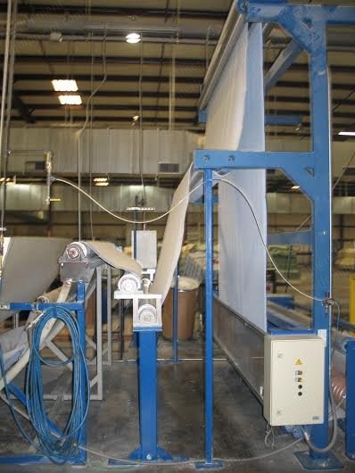
Machine status: Currently not running, stopped on mill floor
Item 001: Rollholder trolleys spool
Item 002: Motive head with brake for rollholder trolley
Item 003: Inspection unit for the material with cutting and sewing machine and service footboard
Item 004: Centring device for plaited fabric
Item 005: Accumulator 60 mt capacity
Item 006: 2-roll pulling unit
Item 007: Service footboards
Item 008: Multivalent coating head (blade + engraved roll) with electronic controls
Item 009: Pre-dosing units
Item 010: Flock dosing units
Specifications
Width of final product: 100" (2540 mm)
Flock dosing width: 108.3" (2750 mm)
Coating width: 101.6" (2580 mm)
Nominal cylinders width: 110.2" (2800 mm)
Mechanical speed: From 0 up to 50 mt/min
Adjustable speed: From 5 up to 50 mt/min
Production speed: From 25 up to 35 mt/min
Speed synchronization: AC drive system
Adjustable oven temperature: From 50° to 200° C
Heating: Natural gas or propane gas
Max tension on the material: 50 kg
Power electric voltage: 440 volt/60 Hz, 3 phases
Auxiliaries electric voltage: 110 volt/60 Hz
Voltage tolerance: ± 6%
Rated wattage: 110 kW
A.C. motors protection: IP55 - CE
Electrical installation: IP55 - CE
Rated thermal power: 1,500,000 kcal/h
Absorbed thermal power (+/-): 1,200,000 kcal/h
Compressed air pressure: 6 bar, 3 m³ per hour
Layout and overall dimensions: Drawing no. 2002-FL-020/3
Item 001 - Rollholder Trolleys Spool
Diameter: 1500 mm
Model: CS/1/1500
Each composed of: 1 frame of structural sections joined together by stiffening bars and with four wheels, two fixed and two movable
1 pair of supports for square bar of 40 mm
1 mechanical pre-arrangement on one side of the trolley to connect a possible motive head
No. 1 guide fixed to the floor
Quantity: 4
Item 002 - Motive Head With Brake For Rollholder Trolley
Model: TM/FR/1
Composed of: 1 frame made of thick welded and bent sheet-steel
1 telescopic cardan shafting for connection to the axle of the roll-holding trolley
1 pneumatic brake with electronic adjustment device for automatic braking checked by a sonar
Quantity: 3
Item 003 - Inspection Unit For The Material With Cutting And Sewing Machine And Service Footboard
Model: GR/BC/PED
Composed of: 1 structure of steel sections for fixing at the floor, with frame to place a service foot-board
1 pneumatic brake with pressure control, manometer and loosening lever
1 idler roll 115 mm diameter
1 travelling carriage mounted on bearings for the fastening of the sewing machine (excluded from the scope of supply)
1 service foot-board with a base made of wood and two idler supporting rolls of 115 mm diameter
Quantity: 5
Item 004 - Centring Device For Plaited Fabric
Make: "E+L"
Composed of: 1 solid frame made of steel connected by stiffening bars
1 rubberised roll ∅ 250 mm to pull the material
1 A.C. gearmotor of 2.2 kW to control the pulling roll ∅ 250 mm
1 idler roll ∅ 115 mm for material passage
2 guiding bars for material tensioning
1 fabric centring system make "E+L" model SRA 8302 composed of one oscillating roll ∅ 100 mm, edge infra-red reader, pneumatic actuator, safety protections, manual sensor positioning
Quantity: 6
Item 005 - Accumulator 60 Mt Capacity
Model: ACC/60
Composed of: 4 structures of sheet-steel connected by stiffening bars both in the lower and in the upper part
1 movable upper frame of steel sections, with a set of idler rolls of 116 mm diameter
1 fixed lower frame of steel sections, with a set of idler rolls of 146 mm diameter
2 pneumatic pistons without rod for opening of upper frame
2 idler transmission rolls of 158 mm diameter placed one at the inlet and one at the outlet side of the accumulator, for the transmission of the material
Quantity: 10
Item 006 - 2-Roll Pulling Unit
Model: GR/T/2CG
Composed of: 2 frames made of worked sheet-steel, connected by stiffening bars
2 steel rolls diameter 250 mm, with rubber-coated surface
1 AC gear-motor of kW 2 to control the 250 mm diam. rolls
2 steel idler rolls of 115 mm diameter with chromium-plated, polished and turned surface
Quantity: 7
Item 007 - Service Footboards
Model: PED/S
Each foot-board is composed of a framework of steel sections with a wooden base and two idler rolls of 115 mm diameter for the passage of the material
Quantity: 2
Item 008 - Multivalent Coating Head (Blade + Engraved Roll) With Electronic Controls
Model: BSP/POLI
Composed of: 2 frames made of welded sheet-steel, connected by stiffening bars
1 supporting roll of diameter 400 mm, with rubberised surface 85 sh., (eccentricity tolerance: max ±1/100 mm)
2 idler rolls of 115 mm diameter
2 uprights made of cast iron, containing the pneumatic pistons for elevation and lowering of the blade
1 synchronisation system, right and left, for the simultaneous fast elevation and lowering of the blade
1 AC motorised synchronising system for the horizontal movement of the blade unit with respect to the supporting roll
2 micrometric devices, each one driven by a 0.2 kW AC gear-motor for the adjustment of height between blade and supporting roll
1 AC motorised system for 180° rotation of the unit containing the blade-holder
1 blade/roll holding unit made of bent, welded and worked sheet-steel, with arrangement to fasten 1 doctor blade and 1 dosing (engraved) coating roll
1 doctor blades, shape chosen by the customer
1 engraved dosing roll diam. 170 mm (engraving at customer’s charge), easily de-mountable, driven by A.C. gearmotor of kW 1
2 lateral coating width limiting devices for the doctor blade
2 lateral coating width limiting devices for the dosing roll
2 counter-blades to distribute the resin on the dosing roll
1 AC gear-motor of 1 kW to control the dosing roll
1 AC gear-motor of 2.2 kW to control the counter-roller
1 resin feed-box in front of the doctor blade
1 recovery tank placed under the counter-roller
1 electronic push button panel with PC light, with adjustment and digital display of the following machine functions: rotation of the blade/roll-holder in prime of degree (adjustment by encoder signals); micrometric regulation of the clearance between the blade/dosing roll and the counter-roller in hundredth of millimetre controlled by optical lines (this last adjustment can be set both simultaneously and separately on the right/left sides); horizontal movement of the blade/roll holder unit (adjustment controlled also by mean of optical lines)
Options, included in the price: 1 level check probe for resin in feed-box
1 pneumatic resin distributor for foamed and non-foamed adhesive
1 auto seam detector with sensor
Quantity: 29
Flocking Machine With 4 Double Dosing Heads (8 Brushes) For Dc-Flock
The machine is designed for the processing of all types of cut flock fibres known on the market for direct charging systems
The electrostatic equipment of the machine is designed according to the valid VDE regulation VDE 0147
Item 009 - Pre-Dosing Units
Welded steel plates chambers
The dosing chamber is equipped with wooden shafts dosing the flock into the flock dosing unit
2 gear motor
0.55 kW
Quantity: 4
Item 010 - Flock Dosing Units
2 welded steel plate dosing chambers with a puncture-proof insulation on the outside
The dosing chamber is equipped with two brush shaft with ball bearing and with joint-ring sealing
Mounted onto the brush shafts are the holders for the brush strips with accurate spacing and clamping device
Request a Quote
✓
Request sent
Thank you, our team will reply to you shortly.
Direct access to our team
Email American Plant & Equipment
Tell us what you want to buy, source, finance, or sell. A machinery specialist will follow up with you.
✓
Thank you. Your request is with the American Plant and Equipment team.
A machinery specialist will follow up with you.
Machinery updates
Subscribe to our email list
Tell us which industries you follow and we will send you the machines that match.
✓
You are on the list.
We will email you when machines that match your interests come in. Unsubscribe from any message.