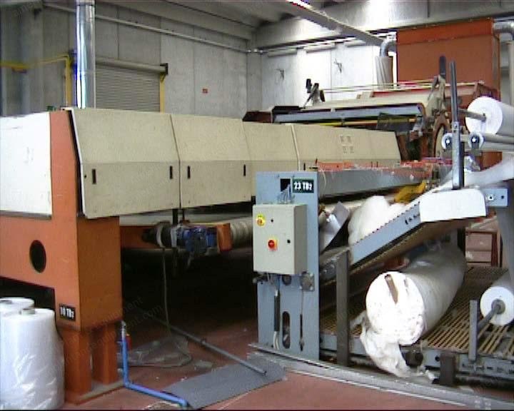
Sicam, Thermobonding Oven, 1998, 4100mm Working Width, 8000mm Heated Zone, 2 Gas Burners
Scroll to zoom
100%
Description
Overview
Inventory number: E-9365
Thermobonding oven
Year: 1998
Manufactured article: Thermobonded wadding
Weight range from 100 to 600 gr/sqmt
Specifications
Working width: 4100 mm (161 inches)
Conveyor width: 4300 mm
Heated zone: One layer with a length of 8000 mm
Overall length: 12,970 mm long
Heating by: Two direct gas burners
Mechanical speed: Up to 30 m/min
Installed electric power: 44 kW approx. for ventilation
Entrance clearance: Up to 300 mm material thickness
Automatic temperature adjustment
Drying and thermobonding temperature: 90 °C – 200 °C
Ventilation: Semi-closed system with centrifugal fan
Exhaust: By independent fan
Adjustable conveyor speed by a.c. motor
Main electric panel
Cooling device with independent section
Drying Chamber
Thermal insulation is achieved through a steel frame fitted with insulating panels, whose inner side is in iron plate.
Inspection doors are provided for an easy access to all the driving parts and for the observation of the drying process.
Conveyor consists of a glass-fibre net, teflon coated and suitable for the required temperature.
It runs through a set of air distributors.
The hot air comes, with perfect uniformity, from the upper blowers and after the contact with the material is recovered by suction.
The aerothermic chamber is provided with centrifugal fan, which feeds a duct for the air distribution.
The drying process is effected in a half-closed cycle, the fanning cycle is with closed cycle, but after each passage the thermo hygroscopic power of the air is set up again by means of the expulsion of a little part of damp air and the passage through the heating device.
Direct Gas Heating
The plant is provided of two gas burners with adjustable temperature.
In this case the flue gas is directly mixed with the ventilation air, avoiding all the heat leakages.
It has the following advantages: very low consumption, precise temperature adjustment, very easy maintenance, fast reaching of the running temperature, the heating ducts are incorporated in the drying chamber (no heat leakage), the heating plant is of low thermal inertia, temperature adjustment is done by flame variation.
The burner has automatic starting and a photoelectric cell safety device.
Gas flow is regulated with a thermostat set at the ventilation temperature.
The combustion chamber, made of refractory steel, is cooled with the forced flow of the ventilation air; in this way it acts as first heat exchanger.
Automatic Temperature Regulation
It is obtained with remote controlled valves, driven by electronic devices.
Cooling Section
Cooling section at the exit, 2 meters long, to cool the web.
The cooling action is by air suction, through the material, by means of an independently driven fan.
Electric Panel
The dryer is equipped with a functional and complete electric panel.
All the electric apparatus, other than the series of stop valves, are equipped with protection devices with automatic disconnection.
The a.c. electric motors are equipped with an electromagnetic remote controlled motor protector.
All the electric apparatuses are arranged in a functional cabinet.
Supply Limits
All the connections with the outside are excluded and i.e.: the exhaust pipes from the connectors on the dryer, the gas piping, the eventual pipe for compressed air and for the water, the electric connection from the line to the panel and from the panel to the machine, all the joining pipes from the dryer to the filtering plant or to the exhaust ventilators and from this one to the outside, eventual building works, the insulation of the ducts.
Included
Electric panel
Cooling section with new conveyor belt
Pictures and drawing available
Request a Quote
✓
Request sent
Thank you, our team will reply to you shortly.
Direct access to our team
Email American Plant & Equipment
Tell us what you want to buy, source, finance, or sell. A machinery specialist will follow up with you.
✓
Thank you. Your request is with the American Plant and Equipment team.
A machinery specialist will follow up with you.
Machinery updates
Subscribe to our email list
Tell us which industries you follow and we will send you the machines that match.
✓
You are on the list.
We will email you when machines that match your interests come in. Unsubscribe from any message.