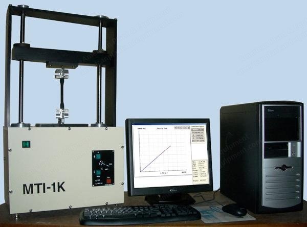
MTI, MTI-1K, 1000 lbs (5kN) Capacity, 115V, Single Phase
Scroll to zoom
100%
Description
Overview
Mti-1k mini 1,000 pounds (5 kn) universal testing machine
Mti-1k high stiffness load frame
One 1,000 pound force tensile/compression load cell
1,000 pound capacity tensile grips
Universal joint and linkage rods for required tensile grips connections
Mti ad-24 automatic 24-bit load signal conditioner subsystem
Mti ad-24 automatic 24-bit strain/deflectometer signal conditioner subsystem
Crosshead displacement measurement and reporting to a resolution of 0.00001 inches
Installation and operational training instruction manual
All testing programs shall be supplied
Specifications
Frame dimensions: 44 inches high, 24 inches wide, and 10 inches deep
Frame weight: less than 100 pounds
Testing region size: 18 inches wide between loading screws
Crosshead travel: 26 inches end-to-end
Testing region: below the moving crosshead, in tension or compression
Testing speeds: 0.0001 inches to 10 inches per minute standard; other speed ranges are available upon request
Displacement resolution: 0.25 microns (0.00001 inches) at standard test speed range
Control: mti c-das pentium iv for computer control of testing; manual control for test setup
Utility requirement: 115 volt, single phase 10 amp ac circuit for load frame and control system; a dedicated surge protected circuit is suggested
Automatic Force, Displacement And Strain Measurement
Force and displacement and strain measurements are automatic
Mti ad-24 automatic 24-bit force and strain signal processors are supplied with each system
The two ad-24's provide data accuracy and measurement resolution approaching one part in one hundred thousand in a fully automatic mode of operation
The load frame crosshead displacement measurement is also automatic, with resolution of 0.000005 inches for all tests
Load Frame Features And Furnished Accessories
Tension and compression testing can be performed in the test bay
Two precision acme screws provide smooth, precise crosshead motion under the full operating load range
The loading crosshead surfaces are ground to precise flatness and parallel standards
Each crosshead surface is fabricated with a mounting bolt circle that provides a means of attaching the system load cell or universal joints or any of a large assortment of testing fixtures to any of the surfaces
A universal joint and linkage for attaching to tensile wedge grips or similar test fixtures is furnished
A universal tension/compression pancake load cell of the frame capacity is provided with system calibration through the mti ad-24 automatic 24-bit load cell signal conditioner; a lesser force cell will be substituted upon request
A high resolution optical encoder coupled to the frame rotating components furnishes crosshead displacement measurements for test programs, and also provides the control system with closed loop feedback to assure constant crosshead travel rate under all load conditions
The system will be furnished with software to control the test and display and process data
A wide range of standard and non-standard materials testing programs is furnished as part of the system
Physical Configuration
Control system: closed loop servo control of crosshead rate
Speed selection: variable potentiometer for manual control, 0-100% of full velocity; speed selection under computer control is infinitely variable
Manual direction and rate controls are provided to allow for movement of the crosshead in both directions at variable speeds ranging from zero to the full travel velocity for setup requirements
All testing will be performed under mti c-das computer control which allows for programming of velocity of the crosshead up to specified programmed travel limits and for changing crosshead velocity based upon programmed values of load or stress or strain or displacement
Signal Conditioning
One mti ad-24 automatic digital signal conditioner will be furnished to condition and encode the system load cell
A second mti ad-24 input system is provided to condition and encode any additional bridge-type sensors such as strain extensometers or deflectometers
The system load cells are automatically conditioned and encoded using the ad-24 digital conditioning system
This fully automatic, stand-alone subsystem acquires and encodes force data at 24-bit resolution
Resolution of 0.05 pounds is typical for a 1,000 pound load cell
Overall accuracy is 0.025% of full scale
Calibration and tare offset nulling are performed automatically
For setup and calibration the operator need only select the load cell from a screen menu of load cells installed in a system
All calibration, zeroing and autorange functions are performed automatically and without further operator intervention
A second ad-24 signal conditioner is furnished to provide similar automatic conditioning of strain transducers or similar bridge-type sensors if ever required
Load Cells, Universal Type, Interchangeable
A 1,000 pound capacity universal load cell shall be furnished along with mounting hardware for ease of attachment within the system load train
Additional load cells in force capacities as low as 5 pounds are available, if required
Load cells can be added to the system at any time and need not be purchased at the time of initial order
Tensile Grips
A set (two) of tensile grips shall be provided
A set of cross-hatch file face inserts is included with the grips
One thousand pound capacity grips are offered, but other sizes are available
Crosshead Displacement
Crosshead position shall be automatically measured by coupled optical encoder
Resolution shall be 0.000005 inches over the full range of travel
Real-Time Graphics
Real-time x-y plots shall be generated on the system monitor with hard copy to the system line printer as required
The operator shall have the option of plotting either stress vs. strain or load vs. deflection as desired
Any selection of ranges can be plotted, and all graphic displays shall auto-range to appropriate scales as a test proceeds
Request a Quote
✓
Request sent
Thank you, our team will reply to you shortly.
Direct access to our team
Email American Plant & Equipment
Tell us what you want to buy, source, finance, or sell. A machinery specialist will follow up with you.
✓
Thank you. Your request is with the American Plant and Equipment team.
A machinery specialist will follow up with you.
Machinery updates
Subscribe to our email list
Tell us which industries you follow and we will send you the machines that match.
✓
You are on the list.
We will email you when machines that match your interests come in. Unsubscribe from any message.