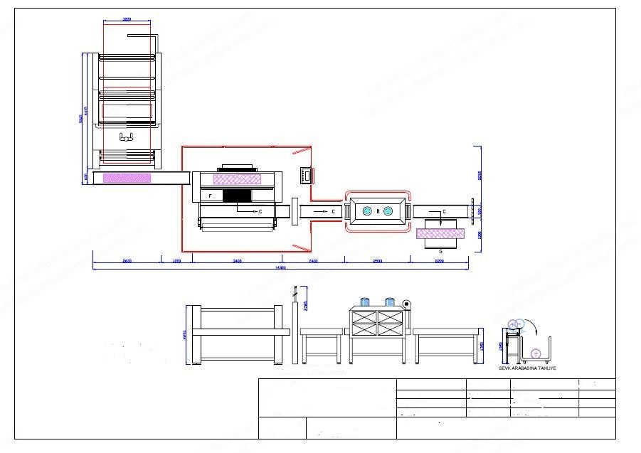
GCM, PM50T, Roll Pack Machine, Width 900-2400mm, Capacity 100 Rolls/Hour
Scroll to zoom
100%
Description
Overview
50 ton packing capacity.
Roll width: min. 900 mm - max. 2400 mm.
Roll diameter: min. 150 mm - max. 500 mm.
Weight of roll: max. 100 kg.
Max. nylon width: max. 3200 mm.
Nylon thickness: 80-120 micron.
Packing capability: 100 rolls/hour.
General Process
Rolled fabric is loaded to conveyor band placed at inlet side of the packing machine, then operator presses start button.
Roll that comes to inlet side is centred to the packing nylon before its diameter and length are measured.
Roll that is bowled by the pushing arm is declined to the packing board by staying on the nylon film.
When the width welding upper jaw declines, it wraps one tour of nylon film on the roll, then it is cut by welding.
Both edges of the fabric roll's nylon, which is transferred to closing band, are cut one by one; overplus nylon is collected to cabin by vacuum.
Roll is passed through the shrink cabin for tight and without emptiness packing.
Packaged rolls are discharged and toppled to one carriage at the end of the conveyor band by leaning to one side of this band.
Between load to roll and bowl to roll, all processes are realized automatically.
Conveyor Band (C)
Two conveyor bands placed at entrance of packing machine, each with length 4.40 m and height 1.00 m.
Operator loads the roll over band and presses start button for automatic packing operation.
Roll Inlet (1)
Roll is transferred to machine by conveyor band, then length and diameter are measured by photocell, and it waits at the middle of the conveyor band.
Nylon Inlet (2)
Two different width nylon (four pieces) can be placed on the nylon feeding platform in front of the machine.
Nylon placement is made manually, but during packing process the nylon feeding operation is realized automatically.
When one of the nylon finishes, the machine stops and gives a voiced alert.
The welding unit assembled on the nylon feeding part is gathered with nylon films.
Nylon has to be suitable for shrink packing operation.
Propulsion Arm (10)
The roll placed on inlet band stays on the nylon film by the aid of pushing arm, then it is bowled to packing tray.
To not damage the nylon, the edge wrinkled nylons of the packing roll are opened by insufflating air.
Packing Tray (3)
When the tray is declined to determined height according to roll diameter, the centre of the roll and upper thermal jaw meet at the same line.
At the end of the welding process, packing tray goes up again and roll is bowled over to the edge closing band.
Lengthways Welding (4)
Lengthways welding system consists of two thermal jaws: fixed nether jaw and locomotive upper jaw; it makes sticking operation with thermic system.
When the roll enters packing tray, upper jaw goes down to wrap the nylon to roll, then connects with nether jaw; after thermal welding operation, nylon is cut by thermal wire.
Nylon Outlet (8)
Continuity of lengthways welding: nylon edge is held by cylinder.
During welding operation, track line of the welding must not coincide with other welding line; for this, nylon is moved 20 mm after each welding operation.
Closing Band (7)
Closing band, which supplies entry and exit of rolls to closing unit, consists of two different units.
Height of bands is suitable for discharging the roll to carriage (enter band height: 1350 mm, exit band height: 1350 mm for transfer to carriage).
Edge Closing (5)
System consists of two active units as upper and nether jaw and makes thermal welding; edge of roll is welded one by one.
Welding jaw proceeds pneumatically; two jaws meet at the centre of the roll.
Welding operation is made with resistance wire; outside of the welding line is cut by same wire; overplus nylon is vacuumed by fan and collected in cabin.
For orderly edge closing operation, carton board and fabric width have to be the same length.
Shrink Cabin (H)
The roll wrapped by nylon is transferred to the shrink cabin by conveyor band for tightly and smooth packing.
Carriage (G)
The roll packed by nylon can be transferred by conveyor band placed at the end of the discharge band, then is bowled to carriage, which can be placed on right or left side.
Length of band is 2.75 m, height is 1.35 m; it bowls over the roll to the carriage by slanting it at one side.
Command Panel
Command system is controlled by PLC and the system process proceeds fully automatically.
Main control circuit is in command panel placed next to machine.
Digital panel is placed on the command panel; selection of manual or automatic operation can be made.