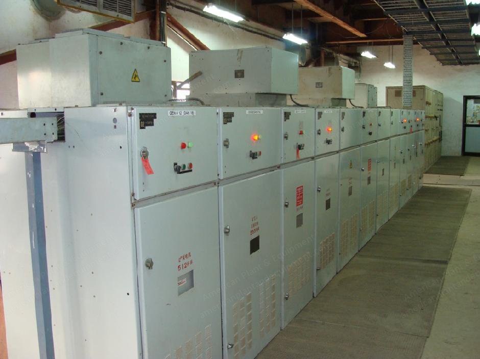
Four sets of Sulzer France make 16 ZAV 40 S type diesel engines, each with a capacity of 10.56 MWe.
Incorporated with a latest PLC-based condition monitoring and equipment protection system along with SCADA.
Diesel engines were manufactured by Sulzer in 1991.
Engine is designed for burning LFO (light diesel fuel) or HFO (heavy fuel oil).
These four DG sets were converted for dual fuel (DF) operations in October 2011.
With the conversion, sets were operated on natural gas as a main fuel and HFO or LFO as a pilot fuel.
Solenoid operated gas admission valves (SOGAV) and Woodward governing system is in use for safety in gas operations.
Average ratio of gas and oil at efficient and safe operation to run the sets is about 60 to 65% gas and 35 to 40% HFO or 70 to 75% gas and 30 to 25% HSD.
LFO is used during starting and stopping of the engines.
GEC Alsthom make alternators are coupled with each DG set and power is generated at 11 kV/50 Hz voltage level on the generator terminals.
This is further stepped up to 110 kV by a single 56 MVA transformer.
The power plant has two service transformers, one 1100 kVA and one 1600 kVA.
The generators have 30,000 to 40,000 total operating hours today.
Complete strip down overhaul of all four diesel engines and turbochargers has been done in 2010-2011.
During strip down overhaul, major components like cylinder liners, 3 turbocharger rotors, pump elements, nozzles, valves, etc. were renewed.
Since this major overhaul, the engines operated only 300 to 400 hours.
Fuel Oil System
The maximum requirement of fuel oil is 3 tons/hour in DF mode and 10 tons/hour in liquid fuel mode.
One main HFO storage tank equipped with three electrical suction heaters provides storage capacity of 480 m³.
Electrical suction heaters maintain the temperature of HFO and no electrical heat tracer and insulation is considered for the main HFO tank.
HFO from road tankers is unloaded by 2 HFO unloading pumps (1 working + 1 standby), each of 30 m³/hr capacity, and is led to the main HFO storage tank.
From the main storage tank, HFO is transferred to a settling tank of 120 m³ capacity.
The settling tank is insulated and provided with electrical heat tracer.
HFO transfer pumps (1 working + 1 standby) of 20 m³/hr capacity are used for transferring oil from main HFO tank to settling tank.
HFO from settling tank is fed to the separators (Alfa Laval MOPX 309) for purification and clarification.
Clean fuel coming from separators is stored in a day tank of 120 m³ capacity.
Natural Gas Fuel System
Natural gas pressure reduction and heating skid reduces the 25 bar gas pressure to 4 bar in downstream line as required by the engines and heats the natural gas to the required temperature of 15 to 20 °C.
Heating of natural gas helps in preventing condensation and entering of moisture in the electrical control valves, preventing malfunction of electrical equipment.
NG pressure reduction skid: make Emerson Process Management.
Inlet pressure: 23 to 25 barg.
Outlet pressure: 3 to 4 barg.
Flow rate: 0.022 to 0.22 mmscmd.
Outlet temperature: 15 to 20 °C.
Heater: Thuba Swiss make, 3 banks total 100 kW.
Lube Oil System
Lube oil from road tankers is unloaded by 1 lube oil unloading pump of 10 m³/hr capacity and led to the lube oil storage tank of 20 m³ capacity.
Transfer of lubrication oil from the lube oil storage tanks to engine lube oil system tank (dry sump) is transferred by oil transfer pumps.
Lubrication oil is filtered with Alfa-Laval MOPX 309 separator and fine filters.
Used lubrication oil from the engine system tank can be transferred by used oil transfer pump to used lube oil storage tank of 20 m³ capacity.
The lubricating oil system consists of a dry sump arrangement with a separate LO tank for cylinder lubrication and bearing lubrication.
Bearing lubrication is done by electrically driven pumps.
Cylinder lubrication is done by the engine mounted hydraulic pump driven by the pressurized bearing lube oil; in case of emergency, done by hand driven pumps mounted on the engine.
Charge Air and Exhaust Gas System
AAF made oil bath suction air filters are installed in the suction line of turbochargers.
Acoustic silencers are installed at the AAF filters.
All charge air coolers are brand new in the charge air system (installed in 2011).
SOGAV valves are installed on the charge air bend just before the cylinder head for natural gas injection.
The structurally supported stack consists of 4 independent uninsulated flues, each of 4 meter diameter and 85 meters in height.
Exhaust gas silencers are installed in the exhaust gas system.
Instrument Air System
For instrument air consumption, 1 instrument air compressor is available connected with a 500 liter instrument air receiver.
This instrument air is used for thermostatic valve operations, operations of engine mounted solenoid valves, and for separators operations.
Start-Up Air System
Air compressors are available along with their accessories such as individual air bottles for engines, distribution piping, etc.
Each starting air bottle has a capacity of 2600 liters and 30 bar working pressure.
In addition to the starting air bottle, each engine is equipped with 2 safety air receivers having capacity of 15 liters and working pressures of 7 bar and 30 bar.
2 of the starting air compressors are Hatlapa make (L80) and 2 are Ingersoll Rand (15T2), both overhauled in July 2011.
Cooling Water System
A recirculation type cooling system with induced draft cooling towers is used for cooling jacket waters from the engines.
The induced draft cooling towers (IDCT) have two cells each of 800 m³/hr capacity and are PVC film type.
The 16 ZAV 40S engines are water cooled by three different systems: jacket water cooling system, fuel valves water cooling system, and raw water system.
Water Softener Plant
Soft water plant with capacity of 500 liters per hour fulfills the requirement of soft water for LO oil and FO separators for centrifuging purpose as well as additional engine cooling water and water for turbocharger washing.
Storage tank for soft water of 10 m³ capacity is installed on terrace of DG room.
Hydrophore unit is connected to tank outlet line for keeping the water pressure constant for various auxiliary requirements in the range of 4 to 6 bars.
Alternators
Generator are GEC Alsthom make with rating 11 kV, 12800 kVA, 0.8 PF, 50 Hz, 500 rpm and rated current of 671.8 A.
This AC generator is driven by diesel engine, air cooled, in open-circuit with suction in basement and discharge in room.
Rotation of the generator is anti-clockwise when seen from back to the engine.
The generator rotor is supported with pedestal type bearing.
The main coupling on diesel side is of the rigid type.
The generator is designed for stress less than elastic limits of metal at over speed of 120%.
Control and Monitoring System
Engine synchronizing and generator and auxiliary transformer protection relay panels.
OCW panel is connected with 11 kV OAK, engine control system new CMR PLC panels and new governor panels for engine control and regulation and synchronizing.
OCW panels consist of protective relays (old relay replaced with new numerical type relay make Woodward model MRA4 only for generator protection for generator breaker), auxiliary transformer feeder, and power transformer feeder.
Request a Quote
✓
Request sent
Thank you, our team will reply to you shortly.
Direct access to our team
Email American Plant & Equipment
Tell us what you want to buy, source, finance, or sell. A machinery specialist will follow up with you.
✓
Thank you. Your request is with the American Plant and Equipment team.
A machinery specialist will follow up with you.
Machinery updates
Subscribe to our email list
Tell us which industries you follow and we will send you the machines that match.
✓
You are on the list.
We will email you when machines that match your interests come in. Unsubscribe from any message.