Power plant nominal output at site condition is 81,300 kWe at generator poles, with each generating set contributing 16,260 kWe.
The plant is designed for operation on heavy fuel oil with light fuel oil as standby/startup fuel.
Operation, control and monitoring of the power plant is carried out via a central control panel and the Wärtsilä operator interface system (WOIS).
The plant started operation in year 2002.
Generating Sets
Five diesel generators, each with a rating of 17,500 kW/unit.
Guaranteed current site output is 16,260 kWe/unit for a design condition of 32°C ambient temperature, 770 m altitude and 40% relative humidity (RH).
Light diesel oil (LDO) is used as start-up and shut down fuel; heavy furnace oil is used as load bearing fuel.
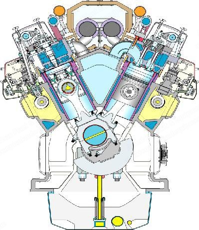
Five Wärtsilä 18V46 engines coupled with ABB AMG 1600SS12 DSEB alternators.
Engine is a 4-stroke, direct injection, turbocharged and intercooled design with 18 cylinders arranged in two banks in ‘V’ type, giving a nominal output of 17,500 kWe.
Direction of rotation facing flywheel is clockwise with a speed of 500 rpm.
Each cylinder has two inlet and outlet valves with 460 mm bore and 580 mm stroke.
Each engine houses two turbochargers (one in each bank) and one turning gear, oil mist detector, charge air cooler, crank case relief valve, governor, and flexible coupling connecting to alternator.
Alternator
Generator is self-cooled, 3-phase, brushless synchronous two-bearing type with an output of 19,300 kVA at 11 kV, 50 Hz generating voltage and frequency, rotating at a nominal speed of 500 rpm (600 rpm overspeed).
Generator has insulation class F and protection IP23.
Excitation power is supplied by an exciter mounted in the generator through a diode bridge, and control power for exciter is supplied by an automatic voltage regulator (AVR).
Fuel System
Two HFO bulk storage tanks of capacity 6,500 m³ each.
One LDO tank of 500 m³.
Two HFO buffer tanks (200 m³ each) and two HFO day tanks (150 m³ each).
Four HFO separators.
Steam System
Three heat recovery steam generators of capacity 1,500 kg/hour each, used for generating steam at 7 bar pressure and 170°C required for heat tracing/heating fuel oil/lube oil.
One LDO fired boiler of capacity 3,000 kg/h is also provided for meeting the steam requirement during black start-up or stand-by period of the plant.
Cooling System
Demineralized (DM) water is used for cooling the primary circuit (engine cylinders).
Raw water/clarified raw water is used in secondary circuit.
Cooling tower with six cells is provided for cooling the heated raw water in secondary circuit.
Electrical System
Electric power is generated at 11 kV/50 Hz using air-cooled ABB made brushless synchronous alternators.
Generators are interconnected at the 11 kV SF6 switchgear with bus sectionalizing.
Power from 11 kV is fed to the grid at 110 kV using two 58 MVA step-up transformers.
Step-up transformers are rated the same even though the normal loading on one transformer will be about 66%, to ensure that in the event of outage of one transformer at least power from three generators can be fed to the grid under these conditions.
The 110 kV switchyard is bussed without bus sectionalizer and the two outgoing lines ultimately feed power to 220/110 kV.
Auxiliary power for the plant is derived from two 2 MVA service transformers.
One 2 MVA service transformer can cater to the entire auxiliary power requirement of the plant.
Request a Quote
✓
Request sent
Thank you, our team will reply to you shortly.
Direct access to our team
Email American Plant & Equipment
Tell us what you want to buy, source, finance, or sell. A machinery specialist will follow up with you.
✓
Thank you. Your request is with the American Plant and Equipment team.
A machinery specialist will follow up with you.
Machinery updates
Subscribe to our email list
Tell us which industries you follow and we will send you the machines that match.
✓
You are on the list.
We will email you when machines that match your interests come in. Unsubscribe from any message.