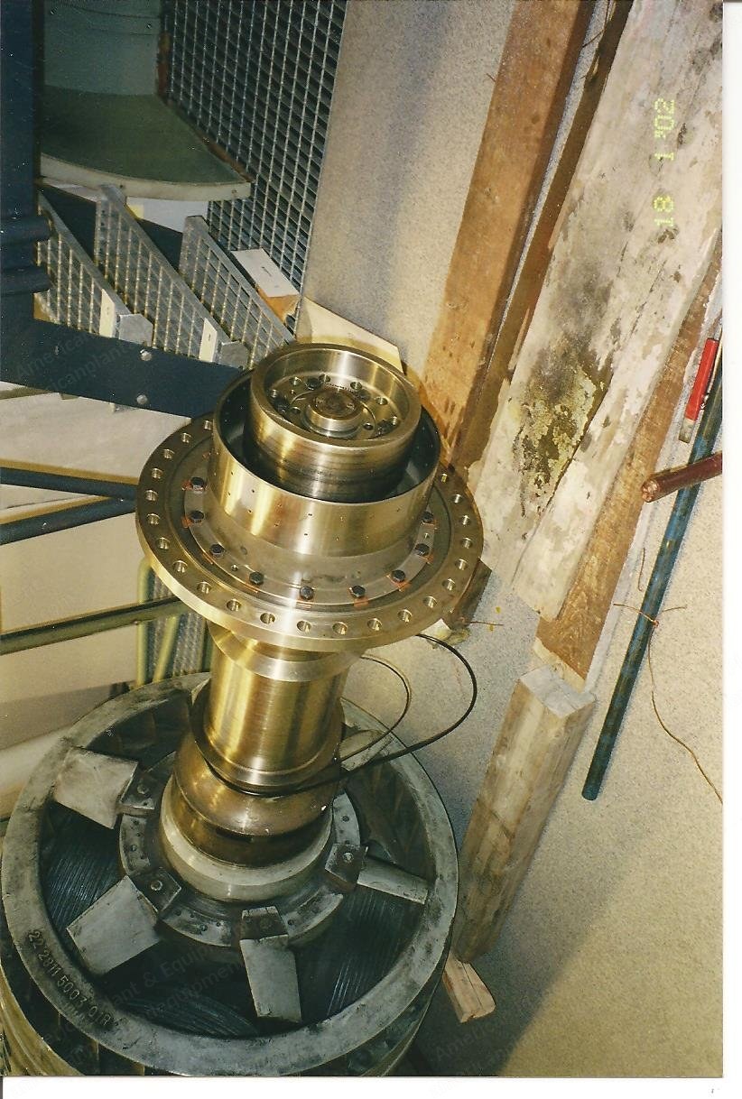
General Electric, AEG, 16.6MW Gas Turbine Power Plant, 50 Hz, 6.3 kV
Scroll to zoom
100%
Description
Key Data
Only 1,200 hours each
Quick start / black start
Output 16.6 MW each
Speed 5,100 rpm
2-stage turbines 5,100 rpm
16-stage compressors 5,100 rpm
Generator AEG; S7083 D4
Power 20,000 kVA
Speed 1,500 rpm
Frequency 50 Hz
Voltage 6.3 kV
General Description
The systems are.
Both systems are identical and are located in the same building.
The systems are installed as mirrored copies of each other and the operator room, maintenance room and control room are located between the two systems.
Only the fire extinguishing system is not duplicated.
The system has water-based and inert gas extinguishers.
System
Each of the inline rotating modules is mounted on a steel beam frame.
With this beam structure the inline and balancing requirements for the systems can be achieved.
In case of transporting it is preferred to keep this structure as complete as possible.
At some points this construction can be divided, but always special attention has to be given to alignment of the axes when installed again.
System Components
One fuel tank
Fuel pumps
Emergency batteries (in case no electricity is available for start up)
Diesel engine for starting
Coupling between starter and turbine
Turbine (incl. noise isolator housing)
Air intake
Exhaust system
Gearing
Coupling turbine
AEG generator (incl. noise isolator housing)
Electricity transformer
Cooling
Controls
Not Included
The buildings and real estate are not included in the deal.
Technical components belonging to the building and real estate like cranes, air conditioning and inside service building are not included.
Fuel Tank
The fuel tank has a storage capacity of approx. 4,000 m3.
It is a standard, general type of round storage tank.
Although this can be part of the deal it is preferred not to include this as the costs of dismantling and transporting the tank as well as handling the fuel would be much higher than building a new one at the new location.
Fuel Pumps
At this moment the fuel pump system is for practical reasons located in a separate small building.
Each system is equipped with an AC and a DC pump.
In case of emergency and electricity is not always available the system can start up with battery power.
Emergency Batteries
For each system a battery pack with sufficient power belongs to the deal.
Due to safety regulations these battery packs are installed in a separate room inside the inside building.
Diesel Engine for Starting
A diesel engine for starting the system is mounted in-line with the turbine axis and coupled with a detachable coupling with the turbine axis.
When the turbine is running at 55% of its operating speed this starter engine is automatically decoupled from the turbine axis and the turbine is increasing its speed up to its stationary by its own fuel energy.
Coupling Between Starter and Turbine
The aim of this coupling is to mechanically couple the starter engine with the turbine.
It is mounted on the same base plate as the diesel starter engine and with this frame mounted on the main structure beams.
Turbine (Including Noise Isolation Housing)
The turbine is of GE brand.
The turbine is equipped for fuel but can easily be changed to gas combustion.
The stationary speed is 5,000 rpm.
A noise reduction is achieved by the housing around the turbine.
Air Intake
The air intake is located outside the building.
The system is mainly space with simple flat filter material.
The air intake system is equipped with two types of heat exchangers.
In case of high moisture content of the outside air, the heat of the exhaust system (400-500 deg C) can be used to dry the external air.
Secondly between the air intake and the turbine the intake air temperature is controlled by a separate heat exchanger.
Exhaust System
A standing pipe of approx. 2.5 m diameter is used for exhaust.
This pipe is provided with heat exchangers to extract the heat from the exhaust and heat up the inlet channel of the air intake to dry the air to be used by the turbines.
Gearing
The gear is of Swiss manufacturing and used to reduce the turbine rotation speed down to a speed required for the generator (50 Hz).
Generator (Including Noise Isolating Housing)
The generator is also mounted on the main beam frame and covered by a noise isolating housing.
Power electronics and voltage regulation components are mounted in and some outside this housing.
The housing is equipped with liquid and gas heat exchangers to control the inside temperature.
The generator brand is AEG.
Electricity Transformer
Near to the generator inside the building a transformer for internal use is located.
Outside the building the main system transformer is located.
This transformer is built on its own frame.
Cooling
The cooling of the main system is done by water.
In this case ground water of 16 m deep is used and pumped back.
In case of another production location the cooling is a point of attention.
Controls
All controls are located in the inside building.
Components used are of German, Swiss and American manufacturers.
Each system has its own control boxes.
One operator screen is available for each system for the operator.
Although completely automated the system is also remote controllable (for this system on location at two places).
The operating system is graphical based on Windows NT Professional.
It is mainly mouse controlled and easy to communicate.
English language is applied.
All relevant variables are measured and registered: temperatures, pressures, operating times, speeds, levels, flows, power, voltages, frequencies, vibrations, limit values, actual values, setting values, fuel, bearings, winding temperatures, etc.
Request a Quote
✓
Request sent
Thank you, our team will reply to you shortly.
Direct access to our team
Email American Plant & Equipment
Tell us what you want to buy, source, finance, or sell. A machinery specialist will follow up with you.
✓
Thank you. Your request is with the American Plant and Equipment team.
A machinery specialist will follow up with you.
Machinery updates
Subscribe to our email list
Tell us which industries you follow and we will send you the machines that match.
✓
You are on the list.
We will email you when machines that match your interests come in. Unsubscribe from any message.