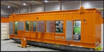
Engine design output: 3,536 kW mechanical on pure diesel; engine output at 1,000 rpm is maximum 2,660 kWe due to camshaft changes for dual-fuel principle (less valve overlap, less air flushing).
3-phase AC power rating: 10,500 V / 50 Hz.
Container Specifications
New built custom container: length x width x height = 12,192 x 3,200 x 3,570 mm.
Inside provided with 80 mm Rockwool insulation with perforated aluminum sheet.
Drip pan to contain 120% containment of all liquids (lube-oil, cooling water, fuel) with three drains.
Engine room personal door on both sides with flush mounted slam shut type door handles and interior panic release handle.
All nuts are lock nuts to reduce hardware from vibrating loose.
Existing container door at the back side.
4-off earthing studs (stainless steel) outside the container.
Partly dismountable roof to allow dismounting engine, generator and silencer in parts, or generator set in one piece.
Access doors at both sides of the container.
2-times large inspection / maintenance doors at engine side.
Generator Description
Continuous power: 2,800 kW.
Air Inlet and Outlet
Air inlet and outlet on top of container by means of air ducts.
Every duct made of galvanized bent steel plate.
Air inlet at the back roof of the container, at generator set.
Air outlet on the front roof of the container, with electrical fan with a capacity of 18 kW.
Both air ducts provided with electrical shutters to avoid rain and snow coming in when the unit is not running.
Engine compartment cooling system sized for a maximum ambient temperature of Δt of 15 °C above ambient temperature.
Fuel System
Container provided with a transfer flange, 3-inch.
Piping from exterior connection to gas train made of stainless steel.
Special pipe with automatic valve in vent line to exterior, in case of emergency.
Engine provided with a 3-inch gas train, including: gas filter, main valve, filter, pressure regulator, double solenoid valve.
Exhaust Gas System
Piping between exhaust gas heat exchanger and exhaust silencer provided with a stainless steel fitting.
Piping provided with Rockwool blankets.
Exhaust air exits the container through one large pipe to reduce air exhaust speed.
Outlet muffler made of stainless steel and provided with a condensate drain.
Exhaust air outlet provided with a stainless steel rain cap against rain.
Exhaust silencers equipped with lifting eyes to facilitate disassembling.
Exhaust silencers mounted on roof.
Heat Recovery
In front of the engine, at the side of the large doors, all coolers etc. built for CHP-part.
Heat recovery of jacket water done by plate heat exchanger.
Heat recovery of intercooler done by separate heat exchanger.
Heat recovery of exhaust gases done by tube heat exchanger made of stainless steel with fixed tubes.
All necessary pumps, valves, thermostat valves, three-way valves and safety valves are in the system.
All needed piping between coolers and engine made of carbon steel.
Piping between exhaust cooler and muffler made of stainless steel.
Cooling System
System I: jacket water; 825 kWth / 90-78 °C.
System III: intercooler 2nd stage; 200 kWth / 35-40 °C.
Thermal energy can be re-used as heat recovery or destroyed by a fin fan table cooler (can be placed on roof or another location near container).
Units have a new dump horizontal radiator, sized for 100 °F and 1000 ft altitude; remote horizontal radiator installed in front of container; installation, pipes, flexible connection by others.
All data by maximum electrical output; see attached ABC-datasheet A-1180/16DZC.
Anti-Vibration Mount
Floor of container defined for good weight repartition.
Shear resistance anti-vibration mounts.
Mounting of anti-vibration mounts under the generator set.
Supply of flexible connections for oil, fuel and water connections.
Electrical
Adequate DC fluorescent light with industrial-grade polycarbonate with timer switches adjacent to personal door.
185 Amp Driesser (or equal) 4-pole LSI motorized breaker accessory 220 VAC, motorized breaker for unit output and paralleling with another engine; connection between the two engines on copper busbar.
Controls enclosure to be water tight.
Shut off AVR at idle speed.
External emergency stop button on each side of the container and on the control panel, adjacent to the personal doors.
Engine and Generator Control
Controls for fully automatic parallel operation per set and controlled by a ComAp controller with touch screen.
Control Functions
Engine Control
Fuel solenoid control.
Engine starter control.
KVA controller cool-down timer.
Oil pressure monitoring.
Water temperature monitoring.
Battery voltage monitoring.
Speed monitoring with over speed protection.
Engine Protective Features
High / low coolant temperature.
High / low oil pressure.
Over speed.
Start failure.
Synchronizing
Digital signal processing to eliminate harmonic issues.
Adjustable phase window, voltage window and dwell times.
Safe dead bus closing logic internal to the control.
Synchronization across generator and main breaker.
Multiple shot re-closing with adjustable time delays.
Real (kW) Load Control
True RMS power calculations accurate control.
Configurable loading/unloading ramp rates.
Isochronous load-sharing of up to 8 units using percentage based load sharing.
Base load control for optimum fuel efficiency.
Import / export control using a watt transducer.
Soft utility transport function.
Externally adjustable base load of process reference levels with independent ramp rates.
KW droop provided for manual load control.
Reactive (kVAR) Control
VAR sharing on isolated bus using percentage based reactive load sharing.
Power factor of VAR control when base loaded.
Externally adjustable VAR or PF set point levels.
Automatic Generator Sequencing
Automatically starts and stops genset, based on plant bus or process demand.
Configurable plant bus demand starts/stop levels and timers.
Generator Protective Features
Over / under voltage.
Over / under frequency.
Reverse power (inverse time delay).
Loss of excitation.
Over current (inverse time delay).
Loss of utility power detection.
Speed / frequency mismatch.
Load surge.
Communications
Modbus or DDE communications via RS-232 based serial port.
RS485 EGCP load-sharing communications network.
Power Output Connections
Copper bus bar.
Connectors in a special case on backside of the unit and hidden behind doors, which can be closed during running the engines, without disconnecting.
Request a Quote
✓
Request sent
Thank you, our team will reply to you shortly.
Direct access to our team
Email American Plant & Equipment
Tell us what you want to buy, source, finance, or sell. A machinery specialist will follow up with you.
✓
Thank you. Your request is with the American Plant and Equipment team.
A machinery specialist will follow up with you.
Machinery updates
Subscribe to our email list
Tell us which industries you follow and we will send you the machines that match.
✓
You are on the list.
We will email you when machines that match your interests come in. Unsubscribe from any message.