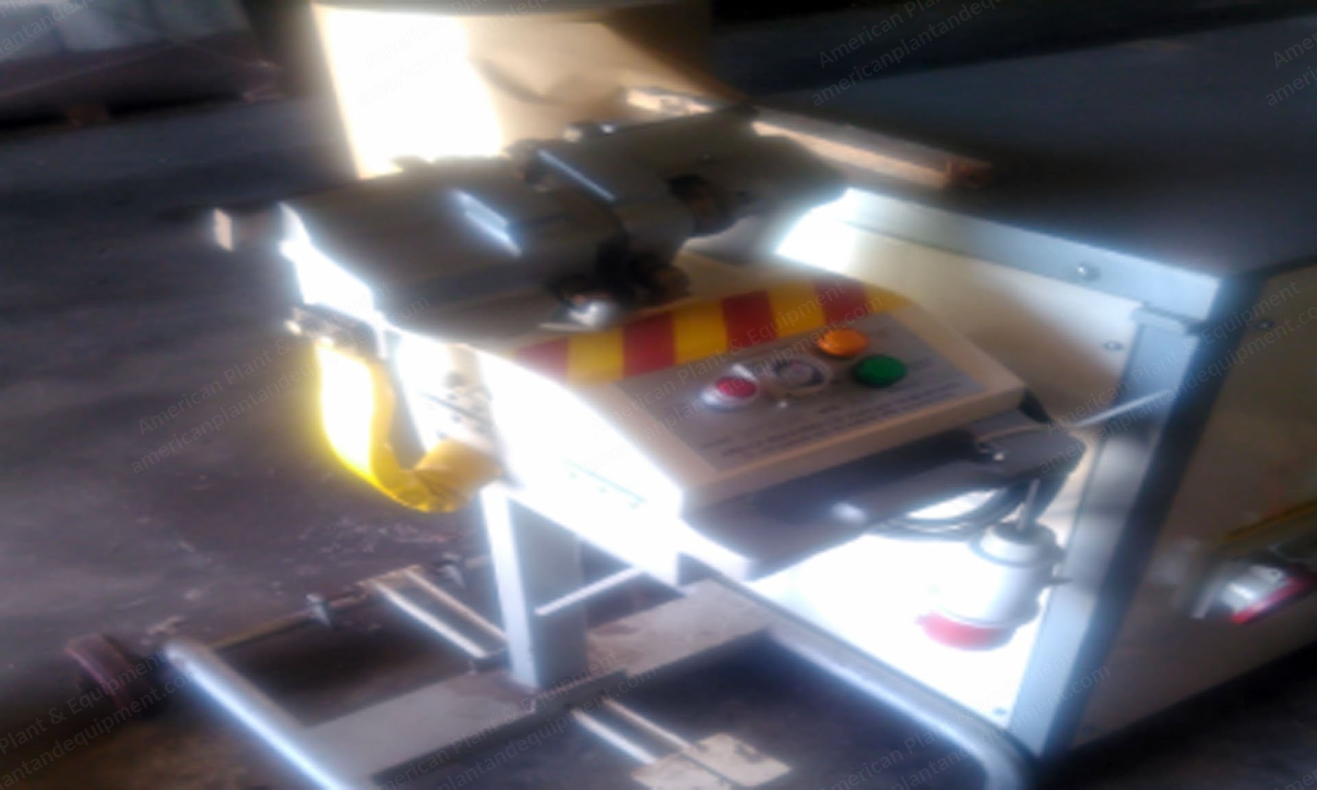
Amelco, WEL4, Butt Welding and Annealing Machine, 220V, 8kW
Scroll to zoom
100%
Description
Overview
Butt welding / annealing machine
Make: Amelco
Model: WEL4
Supplied on wheels for mobility and ready for use
A special socket is provided to be plugged into the frame machine for the electrical supply (8 kW, 220 V, 50 Hz)
Plug in and switch on; the red light on the timer will be switched on indicating that the machine is powered
Two operations to be performed: butt welding and annealing
Electrical Circuit
Except for the mechanical adjustments, there are 4 controls on the machine: power control, welding, annealing, and timer
Power control: a rotary switch on the side of the machine with six steps allows the operator to choose the correct welding power for the particular material to be welded
Welding: the welding will be initiated if the material to be welded is in position and the gap adjustment lever is turned to welding position; the red light will be switched on indicating that the welding is in progress
Annealing: the annealing is operated with the annealing push button
Timer: the timer basically controls the annealing time to eliminate the operator’s judgement and mistakes; it also acts as a cut-off timer during welding in case that the material does not melt (bad contact, wrong alignment, power setting etc.) or the moving part of the welder is jammed
Operation
The gap adjustment lever is set to the correct value (should be more than 1) of 1 to 6
For steel strip 10x1.4 mm we recommend a setting of 3–4 and for 10x1.7 mm a setting of 4–5
The operator, using the pedals, positions the 2 ends of the strip to be welded at the lower part of the jaws resting on the 4 pins; the two ends must meet correctly, in line, touching, clean and at the centre of the distance between the jaws
Choose the correct power 1–6 on the power selector knob
Turn the gap adjustment lever to “welding position” and the welding process will commence
The red light will be illuminated, the material will meld and pushed together
With the pedals depressed, return the welding distance knob to the original position, remove the material from the lower part of the jaws and place it at the upper part of the jaws resting on the 2 pins having the welding point at the centre of the distance between the jaws
Press the red annealing push button; the material will be annealed according to the time and mode set on the timer
Remove the material using the pedals
Adjustments
There are several adjustments available to obtain good welding results
If sparking is observed between the material and the jaws during the welding process, then there are 2 possibilities: a) the conductivity between the material and the jaws is not good (see maintenance), or b) the clamping pressure is not enough; increase the pressure with the clamping lever
The moving part of the jaws should be moving freely and smoothly; clean from any dirt or welding spurs
The side pressure can be adjusted with the rotary pressure knob
Oil regularly at the lubrication point
The welding current can be adjusted using the selector switch at the side to obtain a smooth welding without droppings or gaps between the two ends
The thyristorised timer controls the annealing time (not the welding); adjust accordingly to obtain a change in colour but not glowing red
To achieve the best possible results when annealing, a fully adjustable pulsing signal is generated by the timer; there are 4 controls on the timer: master timer (controls the overall time of annealing), on time (the time during which the electrical current passes from the material), off time (gives a “cooling” or resting time during annealing), and energy level (controls the amount of electrical current passing through the material)
We recommend starting with all controls at “4” and working out the best results for the material used
See the following table for your guidance: material used / controls: 10x2 mm (master timer 6, on time 4, off time 2, energy level 7); 10x1.7 mm (master timer 5, on time 4, off time 2, energy level 6.5); 10x1.4 mm (master timer 4, on time 4, off time 2, energy level 6); 6x1.7 mm (master timer 3.5, on time 4, off time 2, energy level 5.5); 6x1.4 mm (master timer 3, on time 4, off time 2, energy level 5)
Maintenance
The copper jaws, especially the lower part, must be smooth and clean from welding spurs to obtain good conductivity with the material to be welded
There is only one oiling point on the machine that needs lubrication every week with any light lubricant
General cleaning and maintenance is needed for all moving parts using any general purpose grease
Faults and Their Remedies
Fault: red light on timer does not come on. Possible cause: check power supply
Fault: the welding points are glowing red but no melding or side movement to push the material together. Possible causes: 1) check and increase current (1–6); 2) check jaw side movement, clean and oil; 3) increase side pressure
Fault: welding point leaves a gap. Possible causes: 1) reduce current (6 to 1); 2) increase movement of jaws
Fault: welding point looks ok but breaks on bending. Possible cause: check the annealing time and mode and adjust accordingly
Request a Quote
✓
Request sent
Thank you, our team will reply to you shortly.
Direct access to our team
Email American Plant & Equipment
Tell us what you want to buy, source, finance, or sell. A machinery specialist will follow up with you.
✓
Thank you. Your request is with the American Plant and Equipment team.
A machinery specialist will follow up with you.
Machinery updates
Subscribe to our email list
Tell us which industries you follow and we will send you the machines that match.
✓
You are on the list.
We will email you when machines that match your interests come in. Unsubscribe from any message.