
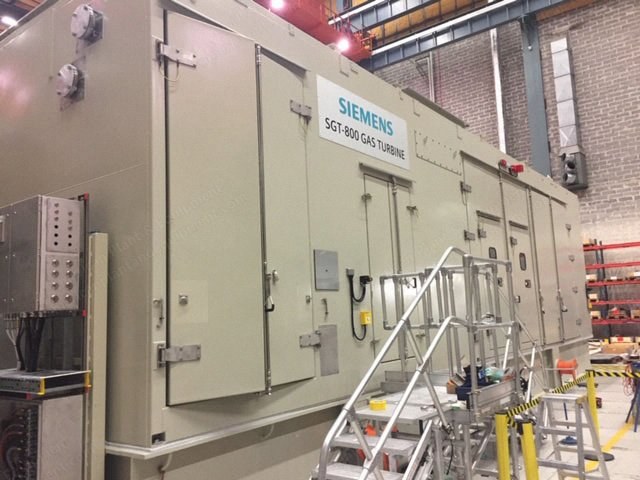
Description
-
Overview
- SGT800, 11 kV, 50 Hz, 56 MW, new, never used, year 2017 - 2018

- SGT800 / 50 Hz
- New
- Never used
- Surplus
- Year 2017 - 2018
- 54 MW as per scope enclosed
- Dual fuel
- Total shipment weight is about - 550 mtons
- Includes full Siemens warranty transferred to customer/buyer
- It is designed for high temp environment 55 C and complete set
-
General
- The SGT-800 has been developed to meet increasing customer demands for highly reliable, clean and efficient power generation equipment.
- Other customer values, such as low life cycle cost, plant compactness and short delivery time, have also been addressed.
-
Designed for Robust Simplicity
- Reliability is a key customer requirement in this market segment.
- Customers are extremely dependent on the smooth and uninterrupted supply of power and heat for their businesses.
- In order to ensure reliability in the SGT-800, its design philosophy has been based upon simplicity, robustness and the use of proven technology.
- The SGT-800 has a frame design with a minimum number of parts in a single-shaft arrangement.
- The compressor rotor and the three-stage bolted turbine module form a single shaft, which rests in two hydrodynamic bearings of the tilting pad type.
- The generator is driven from the cold end of the gas turbine which allows for a simple and efficient exhaust arrangement.
- Modularization, few parts, long component life and easy inspection ensure long time between overhauls and low maintenance costs.
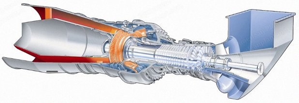
- SGT-800 3-D Cross-Section
-
Design Particulars
-
Compressor Section
- The compressor is of a transonic type with the latest compressor aerodynamic design.
- It has 15 stages and uses controlled diffusion airfoils (CDA) for high efficiency.
- The first three stages have variable geometry.
- To minimise leakage over the blade tips, abradable seals are applied to stages 4-15.
- The vane carrier of the high-pressure section, stages 11 to 15, where the blades are shortest, is made from a low-expansion material that helps keep clearances to a minimum.
- The compressor rotor is built up from discs which are welded together into a robust unit using electron beam welding (EBW), a technology used for many years in the SGT-600 compressor rotor and proven to be a design giving minimum vibrations and very reliable in operation.
- Cooling air for the hot section of the turbine is extracted from the compressor at stages 3, 5, 8, 10 and 15.
-
Combustor Section with 3rd Generation DLE
- The combustor is of the annular type and is made from welded sheet metal.
- The inner surface of the combustor liners and the front panel have a thermal barrier coating which reduces the level of heat transfer and extends the life of the combustor.
- This design concept has been validated in other gas turbines designed by the company.
- Compliance with strict environmental regulations is already required on many markets and the awareness of environmental issues is spreading to new regions.
- The company has recognized the strategic importance of environmental issues and has taken a lead in the control of gas turbine emissions.
- In 1990, the company introduced the 2nd generation DLE (dry low emission) burner to the market.
- The combustor has 30 burners of the 3rd generation DLE design developed in-house.
- The 3rd generation DLE burner technology, as applied to the SGT-800, has NOx emissions capabilities of 15 ppm (15% O2) on natural gas and 42 ppm (15% O2) on liquid fuel and CO emissions capabilities of 5 ppm (15% O2) on natural gas and liquid fuel without the need for water or steam injection.
- The burner can be supplied either as single-fuel or dual-fuel.
-
Turbine Section
- The three-stage turbine is built as one module with tie-bolts for ease of maintenance and bolted to the stub shaft of the compressor.
- It has an advanced aerodynamic design with a fully 3D-analysed flow path with cylindrical sections over the first, second and third stage blades to control tip clearance.
- The airfoils of first and second stage vanes and blades are cooled, using the technology found in other gas turbines, designed by the company.
- The first blade is made of single-crystal material to ensure durability and long life.
- The turbine stator flanges are cooled by compressor air to reduce clearances and improve efficiency.
- The cold-end drive arrangement allows an optimized axial diffuser section to be fitted for better performance.
- Particular care has been taken in the design of the diffuser connection to the heat recovery steam generator (HRSG) to minimise losses in combined cycle and cogeneration applications.
-
Speed Reduction Gear
- The gas turbine is connected to the generator via a speed reduction gear of the double helical parallel type, which reduces the 6600-rpm of the turbine shaft down to a generator speed of 1500/1800 rpm (50/60 Hz).
- The variable speed electric starter motor is also connected to the speed reduction gear, via a self-synchronising and switching (SSS) clutch.
-
Validation of Design
- The first SGT-800 was ordered in 1998 and has been in commercial operation since 1999.
- This unit was delivered to Helsingborg in and has been used for testing during the initial period.
- The tests have included all aspects and components of the gas turbine core engine as well as the auxiliaries and controls, including performance and emission measurements.
- Today more than one hundred units have been ordered by customers around the world.
-
Compressor Section
-
Auxiliary Systems
-
Lubrication
- Since the two gas turbine bearings of the tilting pad type use mineral oil, a common lube oil system can be used for the gas turbine, speed reduction gear and generator.
- Oil pressure is supplied by 3 x 50% AC-driven pumps (2 operating/1 stand-by), which are controlled by static frequency converters (SFC´s).
- The pumps will increase their capacity in excess of 50% in the event of lube oil pressure decrease, avoiding pressure “dips” at pump change.
-
Fuel Systems
- The SGT-800 is capable of operation on a range of gaseous and liquid fuels.
- Two fuel systems are available, for gaseous and liquid fuels, and in dual-fuel operation an automatic changeover from gas fuel to liquid fuel can be performed in a defined load range.
-
Control System
- The SGT-800 control system is based on the SIMATIC PCS7 system and has two controllers from the S7-400 series, one AS417 and one AS417F.
- The AS417 is used for sequencing, interlocks, open loop control and for closed loop control for fuel valve positioning.
- The AS417F is used as a SIL proven safety system.
- The human-machine interface comprises a WinCC operator station with a full graphic colour TFT screen.
- The SIMATIC PCS7 control system may also communicate with external systems via standard protocols.

- Control and Automation Overview
- Installation with Typical Control Room
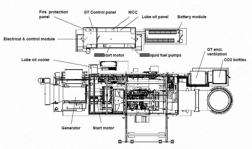
- Typical Simple Cycle Arrangement, Top View
- (Local control module and battery module is optional)
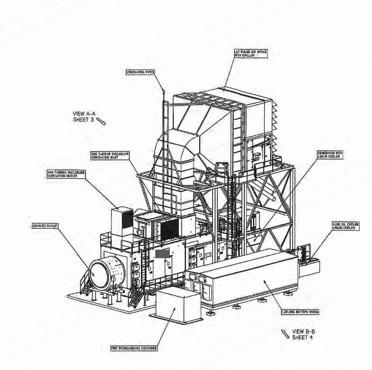
- The SGT-800 installation meets stringent requirements for compactness, short installation and commissioning times and ease of maintenance.
- The gas turbine is skid-mounted, with the auxiliaries grouped in self-contained modules to one side of the main skid.
- The layout is basically the same for all applications, whether simple or combined cycle, indoor or outdoor installation.
- The gas turbine skid is built of steel beams and carries the gas turbine, speed reduction gear.
- It rests on a concrete foundation together with the generator and the foundation may be fitted with spring mounts if necessary.
- The main and auxiliary skids are covered by a weatherproof enclosure extending from the gear to the gas turbine exhaust.
- The generator is placed either below a roof or inside an enclosure, depending on site requirements.
- The air intake is placed on the enclosure roof and the air intake support is integrated in the enclosure structure.
- A two-stage disposable air filter is supplied as standard, but other options are also available, depending on site requirements.
- The exhaust silencer and stack are supported by separate external beam structures.
- Electrical and control equipment may either be installed in the customer's control room or in a separate enclosures containing an auxiliary equipment, control equipment and batteries, see a typical example above.
-
Lubrication
-
Generator
- The gas turbine includes a 4-pole generator type, driven from the cold end of the gas turbine via the parallel speed reduction gear.
- It is of simple and rugged design with a salient pole rotor with solid pole plates and a rotating brushless exciter.
-
Combined Cycle and Cogeneration Applications
- In a combined cycle the SGT-800 can be arranged together with a heat recovery steam generation (HRSG) unit utilising the heat in the exhaust gases.
- A dual-pressure HRSG feeds a single-cylinder steam turbine.
- For greater power, two SGT-800 units, each with its own HRSG, may be arranged to feed one common steam turbine.
- The SGT-800 is also an excellent alternative for cogeneration applications, i.e. when only steam production is required.
- Depending on customer requirement either one or two pressure level HRSG's are possible.
-
Installation and Commissioning
- In order to reduce installation time at site, the SGT-800 comes in modules which have been assembled and stationary tested in the workshop prior to shipment.
- Most of the piping and cabling work has also been carried out on the shop floor to minimise the time required for this at site.
- The gas turbine and gear are mounted on the main base frame make up the biggest shipping module.
-
Starting and Operation
- The SGT-800 is started by means of an electric starter motor connected to the speed reduction gear.
- The compressor has two bleed valves at stages 5 and 10, which are open at the beginning of the starting procedure and close during the start-up sequence.
- During normal operation, the power output is controlled by regulation of the variable guide vane (VGV) and the turbine inlet temperature, TIT.
- When a reduced power output is required, the VGV is closed while the TIT is kept constant until the exhaust temperature reaches 600°C /1112°F.
- Further power output reduction is achieved by reducing the TIT temperature and closing the VGV while maintaining the exhaust temperature at 600°C / 1112°F.
- When the VGV is set to its minimum position, the power output can be reduced further by lowering the TIT.
- At high ambient temperatures the VGV is restricted in order to keep a safe surge margin.
-
Performance
- The SGT-800 aerodynamic design has addressed the market requirements for high efficiency (low fuel consumption) in simple/cogeneration/combined cycles.
- Optimizations of the turbine inlet temperature (TIT) versus the pressure ratio, the use of abradable seals, low-expansion materials in the compressor section, as well as features such as turbine stator clearance control and the axial diffuser, contributes to the high level of efficiency.
-
Low Life-Cycle Cost
- Two key elements of the life-cycle cost are the costs of fuel and maintenance.
- They have therefore been considered at the design stage of the SGT-800 to achieve low costs for the operator without sacrificing basic reliability and availability.
- The basic robustness and simplicity of the SGT-800 and an optimised maintenance schedule mean that the maintenance cost is very competitive.
-
Designed for Ease of Maintenance
- The SGT-800 has a number of features that simplify maintenance and inspection.
- One side of the gas turbine has been kept “clean”, avoiding unnecessary piping, cabling and connections to allow for easy inspection.
- Borescope ports are available on the clean side for inspection of compressor stages.
- At the front of the inlet chamber, 1 manhole with transparent and reinforced polycarbonate window provides for easy inspection of the compressor inlet bellmouth.
- The compressor casing is vertically split in the longitudinal direction, which allows half of it to be removed for easy access to the rotor and stator parts.
- The rotor centerline is 1.5m / 5ft above the floor, making inspections very convenient.
- The "hot section" including the turbine module, the combustion chamber and the burners can be maintained with the gas turbine resting on its normal supports and without moving the core engine out of its installed position.
- This concept saves time and promotes safety at work during maintenance.
- The burner section design allows each of the 30 3rd generation DLE burners to be removed individually without dismantling the machine.
- It also provides for easy inspection of the combustion chamber.
- An overhead crane is installed inside the gas turbine enclosure to facilitate maintenance and enough space is available to allow operating personnel to walk around the machine.
-
Scope of Supply
- This scope of supply is valid for one (1) item of Siemens Industrial Turbomachinery AB’s model SGT-800 54MW gas turbine for power generation, designed for continuous base load operating mode.
- The SGT-800 is a high performance industrial gas turbine suitable for a variety of applications including simple cycle, combined heat and power and combined cycle power plant.
- In order to ensure reliability in the SGT-800, its design philosophy has been based upon simplicity, robustness and the use of proven technology.
- Modularization, few parts, long component life and easy inspection ensure high availability and low maintenance costs.
- Please feel free to contact us regarding your requirements.
- Drain from terminal points.
- Exhaust diverter valve.