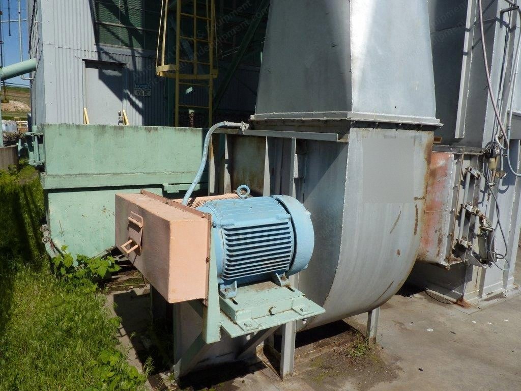
Near new cogeneration system with modular design that has never been run in production.
System is a 1.2-megawatt power plant.
Can burn bark, sawdust, agricultural wastes such as peanut shells, rice hulls, straw, animal residue, wet wood, etc.
Converts waste products into usable thermal and electrical energy.
Solid waste stream can be converted into particle form using a commercial shredder, conveyed to a silo for storage, and then fed automatically into the multi-zone burner.
Steam is generated through a low pressure 275 degree (de-rated from 300 degree) stainless steel boiler with a heat exchanger.
Inlet steam is 475 psig at 700 degrees ftt with a maximum of 22,000 lbs/hour but could be increased to 24,000 lbs/hour.
Exhaust steam pressure is 3" hga at 5449 rpm but designed to run at 4" absolute vacuum.
Steam is transferred to the 3-stage back pressure turbine rated at 1654 hp detuned to 1200 hp to match the generator.
Plant was new in 2005/2006 when installed and has never been run except for permitting function.
Turbine gearbox and generator were oem rebuilt.
Company purchased this system with a guarantee the burner could meet nox standards.
After installation, the burner could not efficiently burn fiber with high formaldehyde content.
Consequently, the burner could not meet those nox standards that are one of the most stringent set of standards in north america.
These multi-stage burners are used throughout north america and meet or exceed nox control standards in other areas without problems.
Included Equipment
3-stage burner boiler egr fan id fan.
Supply water tank.
Service water pump.
Water softener and filter.
Boiler water pump system.
Dual cyclone separator.
Electrostatic precipitator.
Esp transformer.
Esp pump system.
Condenser pump system.
Steam turbine.
Sentinel generator.
Generator control center.
Boiler control center.
Combustion control center.
Plant #2 switchgear.
Control room switchboard.
Turbine oil system.
Dust delivery control system.
Condenser control panel.
Esp control panel.
Turbine oil control.
Plant #1 power switchgear.
Boiler feedwater tank.
Condition
System comes complete with generator control center, boiler control center, combustion control center, control room switchboard, turbine oil system, dust delivery control system, switchgear and plc controls.
This cogen system can be professionally dismantled, all equipment tagged for reinstallation and shipped to your facility, reassembled, and connected to your present electrical grid system.
It would take approximately 10 weeks to dismantle the plant and 15 trucks to ship the equipment to your plant site, and approximately 16 weeks to reassemble.
This plant would include everything needed except fuel processing (grinding), storage and a transformer to supply power to your facility.
Shipment of the plant would be broken down as follows: five 53' trailer vans to legal weight, ten 53' flatbed trailers.
Total weight of cogen plant equipment = 581,000 lbs.
Tie-down gear, chains, blocks and chokes = 6,000 lbs.
Gross cubic setting of cargo = 67,840 cubic feet.
Loading Analysis - Boiler Feedwater Tank
Loadpoint: lp4 footing.
Length: 9.00 ft.
Width: 9.00 ft.
Depth: 0.67 ft.
Count: 1 ea.
Cubic ft: 54.03 cuft.
Total cu ft: 54.03 cuft.
Load cent. ht.: 4.00 ft.
Machine foot length: 6.00 ft.
Machine foot width: 6.00 ft.
Machine foot count: 1.00 ea.
Type: 1.
Machine wt.: 16,000 lbs.
Footing wt.: 8,104 lbs.
Footing load: 197.53 lbs/sqft.
Soil loading: 297.58 lbs/sqft.
Tank assembly is bolted down.
1 = evenly distributed across base.
2 = concentrated footprint approx. psf which is distributed over entire slab.
Loading Analysis - Steam Unit
Loadpoint: lp3 - footing.
Length: 25.00 ft - 13.00 ft.
Width: 14.00 ft - 3.00 ft.
Depth: 1.00 ft - 2.00 ft.
Count: 1 ea - 3 ea.
Cubic ft: 350.00 cuft - 234.00 cuft.
Total cu ft: 584.00 cuft.
Load cent. ht.: 8.00 ft.
Machine foot length: 10.30 ft.
Machine foot width: 1.00 ft.
Machine foot count: 3.00 ea.
Type: 2.
Machine wt.: 53,000 lbs.
Footing wt.: 52,500 lbs.
Footing load: 151.43 lbs/sqft.
Soil loading: 301.43 lbs/sqft.
Boiler assembly is bolted down.
1 = evenly distributed across base.
2 = concentrated footprint approx. 1,715.21 psf which is distributed over entire slab.
Loading Analysis - Condensor Unit
Loadpoint: lp2 footing.
Length: 23.00 ft.
Width: 3.00 ft.
Depth: 3.00 ft.
Count: 6 ea.
Cubic ft: 1,242.00 cuft.
Total cu ft: (not specified).
Load cent. ht.: na* ft.
Machine foot length: 2.00 ft.
Machine foot width: 2.00 ft.
Machine foot count: 6.00 ea.
Type: 2.
Machine wt.: 40,000 lbs.
Footing wt.: 186,300 lbs.
Footing load: 1,666.67 lbs/sqft.
Soil loading: 546.62 lbs/sqft.
Condensor assembly is welded down.
1 = evenly distributed across base.
2 = base pad loading is concentrated.
Loading Analysis - Turbine-Generator Set
Loadpoint: lp6 footing.
Length: 21.00 ft.
Width: 9.00 ft.
Depth: 1.00 ft.
Count: 1 ea.
Cubic ft: 189.00 cuft.
Total cu ft: 189.00 cuft.
Load cent. ht.: 3.50 ft.
Machine foot length: 6.00 ft.
Machine foot width: 6.00 ft.
Machine foot count: 1.00 ea.
Type: 1.
Machine wt.: 38,000 lbs.
Footing wt.: 28,350 lbs.
Footing load: 201.06 lbs/sqft.
Soil loading: 351.06 lbs/sqft.
Assembly is bolted down.
1 = evenly distributed across base.
2 = concentrated footprint approx. na psf which is distributed over entire slab.
Loading Analysis - Combustion Unit
Loadpoint: lp1.
Length: 24.75 ft.
Width: 8.50 ft.
Depth: 1.00 ft.
Count: 1 ea.
Cubic ft: 210.38 cuft.
Total cu ft: (not specified).
Load cent. ht.: 6.50 ft.
Machine foot length: 24.58 ft.
Machine foot width: 7.60 ft.
Machine foot count: 1.00 ea.
Type: 1.
Machine wt.: 80,000 lbs.
Footing wt.: 31,556 lbs.
Footing load: 428.25 lbs/sqft.
Soil loading: 597.17 lbs/sqft.
Burner assembly is bolted down.
1 = evenly distributed across base.
Loading Analysis - Wet Esp Unit
Loadpoint: lp5 footing.
Length: 9.00 ft.
Width: 9.00 ft.
Depth: 0.67 ft.
Count: 1 ea.
Cubic ft: 54.03 cuft.
Total cu ft: 54.03 cuft.
Load cent. ht.: 9.00 ft.
Machine foot length: 6.00 ft.
Machine foot width: 6.00 ft.
Machine foot count: 1.00 ea.
Type: 1.
Machine wt.: 38,000 lbs.
Footing wt.: 8,104 lbs.
Footing load: 469.14 lbs/sqft.
Soil loading: 569.19 lbs/sqft.
Assembly is bolted down.
1 = evenly distributed across base.
2 = concentrated footprint approx. na psf which is distributed over entire slab.
Request a Quote
✓
Request sent
Thank you, our team will reply to you shortly.
Direct access to our team
Email American Plant & Equipment
Tell us what you want to buy, source, finance, or sell. A machinery specialist will follow up with you.
✓
Thank you. Your request is with the American Plant and Equipment team.
A machinery specialist will follow up with you.
Machinery updates
Subscribe to our email list
Tell us which industries you follow and we will send you the machines that match.
✓
You are on the list.
We will email you when machines that match your interests come in. Unsubscribe from any message.