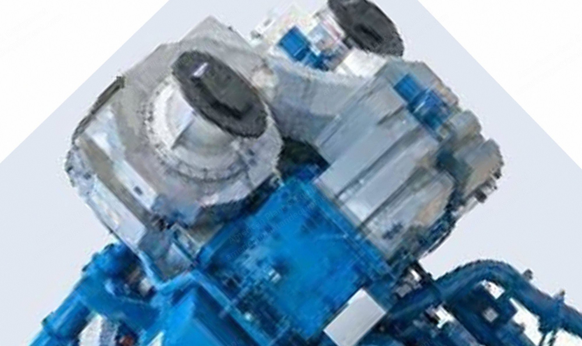
Wartsila, 20V34DF, 2022, 9.75 MW, Dual Fuel Gas Engines, 50Hz
Scroll to zoom
100%
Description
Overview
Gross electrical output approximately 9.75 mw each
Type 20v34df
Dual fuel gas engines
Can be operated with heating oil or heavy oil
Year 2022
Complete new with warranty
The prime movers consist of 2 x wartsila 20v34df type engines, capable of operating on 99% natural gas with one percent (1%) of the energy input provided by diesel fuel as the pilot fuel to initiate ignition or operating on 100% diesel fuel
The sets are capable of switching fuels during operation
Indicative performance values are presented below; final performance will be provided and can be guaranteed after receipt of contract fuel specifications and contract design basis ambient conditions
Configuration
Individual generator set
Type 20v34df: gross output on gas 9780 kwe, plant net output 19,560 kwe, net heat rate per unit 8135 kj/kwh
Type 20v34df: gross output on lfo 9780 kwe, plant net output 19,560 kwe, net heat rate per unit 8640 kj/kwh
Engine Specifications
Wartsila 34df: imo tier iii, epa t3
Cylinder bore: 340 mm
Piston stroke: 400 mm
Cylinder output: 480, 500 kw/cyl
Speed: 720, 750 rpm
Mean effective pressure: 22.0 bar
Piston speed: 9.6, 10.0 m/s
Generator voltage: 0.4-13.8 m
Generator efficiency: 0.95-0.97
Fuel specification: fuel oil 700 cst/50°c 7200 sr1/100°f, iso 8217 category iso-f-dmx, dma and dmb
Bsec: 7590 kj/kwh
Bsgc: 7490 kj/kwh
Performance Conditions
Net performance values above are given at the high side of an assumed step up transformer(s)
Basis temperature for output and heat rate: 30 °c
Basis relative humidity for output and heat rate: 50 %
The net lube oil cons. is increased with a factor of 1.1 (degradation, measurement uncertainty and contingency) and multiplied with the engine specific mcr (shaft power)
The gross lube oil cons. is multiplied with the engine specific mcr (shaft power)
Reference Conditions
The output is available within a range of ambient conditions and coolant temperatures
The required fuel quality for maximum output is specified in the section fuel characteristics
For ambient conditions or fuel qualities outside the specification, the output may have to be reduced
The specific fuel consumption is a statement engines operating in ambient conditions according to iso 15550:2002 (e)
Total barometric pressure: 100 kpa
Air temperature: 25 °c
Relative humidity: 30 %
Charge air coolant temperature: 25°c
Engine Block
The engine block, made of nodular cast iron, is cast in one piece for all cylinder numbers
It has a stiff and durable design to absorb internal forces and enable the engine to be resiliently mounted without any intermediate foundations
The engine has an underslung crankshaft held in place by main bearing caps
The main bearing caps, made of nodular cast iron, are fixed from below by two hydraulically tensioned screws
They are guided sideways by the engine block at the top as well as at the bottom
Hydraulically tightened horizontal side screws at the lower guiding provide a very rigid crankshaft bearing
A hydraulic jack, supported in the oil sump, offers the possibility to lower and lift the main bearing caps, e.g. when inspecting the bearings
Lubricating oil is led to the bearings and piston through this jack
A combined flywheel/thrust bearing is located at the driving end of the engine
The oil sump, a light welded design, is mounted on the engine block from below and sealed by o-rings
The oil sump is available in two alternative designs, wet or dry sump, depending on the type of application
The wet oil sump comprises, in addition to a suction pipe to the lube oil pump, also the main distributing pipe for lube oil as well as suction pipes and a return connection for the separator
The dry sump is drained at either end (free choice) to a separate system oil tank
Crankshaft
The crankshaft design is based on a reliability philosophy with very low bearing loads
High axial and torsional rigidity is achieved by a moderate bore to stroke ratio
The crankshaft satisfies the requirements of all classification societies
The crankshaft is forged in one piece and mounted on the engine block in an under-slung way
In v-engines the connecting rods are arranged side-by-side on the same crank pin in order to obtain a high degree of standardization
The journals are of same size regardless of number of cylinders
The crankshaft is fully balanced to counteract bearing loads from eccentric masses by fitting counterweights in every crank web
This results in an even and thick oil film for all bearings
If necessary, the crankshaft is provided with a torsional vibration damper
Connecting Rod
The connecting rods are of three-piece design, which makes it possible to pull a piston without opening the big end bearing
Extensive research and development has been made to develop a connecting rod
Request a Quote
✓
Request sent
Thank you, our team will reply to you shortly.
Direct access to our team
Email American Plant & Equipment
Tell us what you want to buy, source, finance, or sell. A machinery specialist will follow up with you.
✓
Thank you. Your request is with the American Plant and Equipment team.
A machinery specialist will follow up with you.
Machinery updates
Subscribe to our email list
Tell us which industries you follow and we will send you the machines that match.
✓
You are on the list.
We will email you when machines that match your interests come in. Unsubscribe from any message.