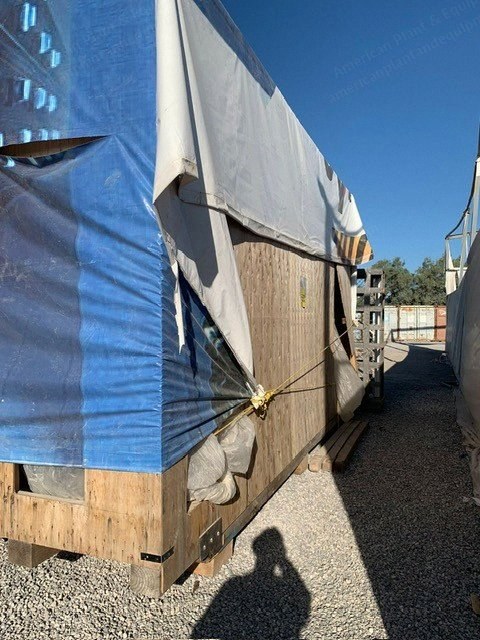
ABB type AMS 800L4P BS brushless synchronous generator rated
Power = 11000 kVA
PF = 0.85 (overexcited)
PF = 0.9 (underexcited)
Voltage = 13800 V
Frequency = 60 Hz
Speed = 1800 rpm
For installation in safe area
Designed for steam turbine
Designed according to IEC 60034-1
Included Accessories
Standards and Site Conditions
UBC4 earthquake zone classification
Main Mechanical Data
Clockwise direction of rotation at drive end, facing shaft end
Protection of machine IP00; final IP degree depending on final duct and filter design
Temperature rise, rotor within class B
Temperature rise, stator within class B
Excitation
Main brushless exciter type GLB 600A for DC excitation complete with diode bridge, thyristors, RC circuits and control box
Mini circuit breaker - PMG over current protection
PMG
Cooling System
Cooling arrangement: IC3 A1; inlet and outlet duct through base or above from the surrounding, self circulation; air filters for the inlet openings
For self- or forced-circulation air with inlet ventilation at DE and NDE side designed with air filter (F6) located directly on the generator top; the hot air outlet will be connected to air duct direct to generator frame and ventilated out from building
Inlet and outlet air flange connection to external duct
Maximum total air pressure drop allowed in the duct is <100 Pa
Shaft Extensions
Coupling half DE mounted by ABB
Coupling to be supplied by others in finish machined condition, ready for assembly on machine; the coupling needs to be supplied to ABB at least 4 weeks before factory acceptance test (FAT); drawings and assembly instructions need to be sent to ABB at least 14 weeks before FAT
Cylindrical shaft end with key in DE
Provision for coupling guard DE
Shaft extension design according customer request
Bearings
Bearing size 18/225
Complete bearing oil connection system to common point, stainless in- and outlet, ANSI
Flow sight glass for each bearing in oil outlet, stainless steel
Forced lubricated sleeve bearing; bearing provided with loose oil ring
Jacking oil including oil pipes, motors and pumps
Lockable oil pressure reducing valve in brass
Inlet oil connection at left side of machine seen from DE, location at DE
Outlet oil connection at right side of machine seen from DE, location at DE
Oil inlet flange: ANSI 3/4" CL 150
Oil outlet flange: ANSI 3" CL 150
The lube oil drain pressure must be less than or equal to the machine ambient pressure; an oil drain pressure of 200-1000 Pa lower than the bearing ambient is recommended
Main Terminal Boxes and Related Accessories
Heaters in main terminal box, safe area, 480 V three phase supply
Main terminal box located on the right side, seen from DE
Main terminal box supply cable entry from below; gland plate is removable, undrilled and of non magnetic material
Standard medium air insulated main terminal box
The main terminal box is delivered as a loose item, assembly on site is not included in ABB's scope of supply
Line Side
3 current transformers, 3 cores, mounted in main terminal box, accuracy class 0.5 (IEC)
3 voltage transformers
Earthing device 3-phase ball bolt including earthing equipment
Neutral Side
3 current transformers, 3 cores, mounted in main terminal box, accuracy class 0.5 (IEC)
2x RTD in cold machine air, duplex (PT100), 3 wire, unshielded (mounted at NDE + DE)
2x RTD per bearing shell, duplex (PT100), 3 wire, unshielded
6x RTD's in stator windings (3 for temperature monitoring and 3 as spare), single (PT100), 3 wire, unshielded, safe and hazardous area
Differential pressure switches for air filter, one each filter
Heaters in both main machine and exciter, safe area, 480 VAC 3 phase supply; the heaters should always be connected during stand still to avoid condensation
Painted carbon steel junction boxes provided with undrilled gland plates; located at left side of machine facing DE
Shaft earthing brush mounted at DE
Vibration control proximity type Shinkawa (2 probes per bearing mounted, 90 deg apart, outboard the bearing centerline)
Foundation and Installation
Long sole plate (ABB std); including anchor bolts, leveling screws etc.
Mounting kit including fastening screws, jacking screws and dowel pins
Mounting shims in black steel, total thickness 2 mm for each machine foot
Special Design and Accessories
Burnishing shaft hub surface for proximity type of vibration probes, maximum combined electrical and mechanical run out 23 pm (0.91 mils) peak-to-peak
Rotor sliding tool - RST2 (one covering all identical units)
Slings, lift jack and rotor storage support for rotor sliding tool (one covering all identical units)
Varnish of rotor coils
Vibration level according to ABB standard (MDD 3AAM100425)
Jack-up support 4 pcs, welded on side of generator AMS 800 rotor sliding tool RST 2
Sliding plates for rotor removal of rotor by sliding, requires one hook lifting with a capacity which can handle the rotor weight, the hook motion must be along the shaft; includes slings, lift jack and rotor storage support
Painting and Corrosion Protection
Painting in special colour, RAL5019
Standard industrial coating acc. to ISO 12944 C3
Packing and Transportation
Seaworthy wooden case packing
Documentation
Installation and maintenance manual in English language (one covering all identical units)
Outline drawing 3D (one covering all identical units)
Painting specification (one covering all identical units)
Preliminary setting list, typical (one covering all identical units)
Standard documents for machine according to MDD 3AAM100439
Test procedures, according to ITP (one covering all identical units)
Transportation drawing (one covering all identical units)
User's manual on CD (1 copies) (one covering all identical units)
Tests and Certificates
According to enclosed test plan 3BSY 200003-HSX
Request a Quote
✓
Request sent
Thank you, our team will reply to you shortly.
Direct access to our team
Email American Plant & Equipment
Tell us what you want to buy, source, finance, or sell. A machinery specialist will follow up with you.
✓
Thank you. Your request is with the American Plant and Equipment team.
A machinery specialist will follow up with you.
Machinery updates
Subscribe to our email list
Tell us which industries you follow and we will send you the machines that match.
✓
You are on the list.
We will email you when machines that match your interests come in. Unsubscribe from any message.