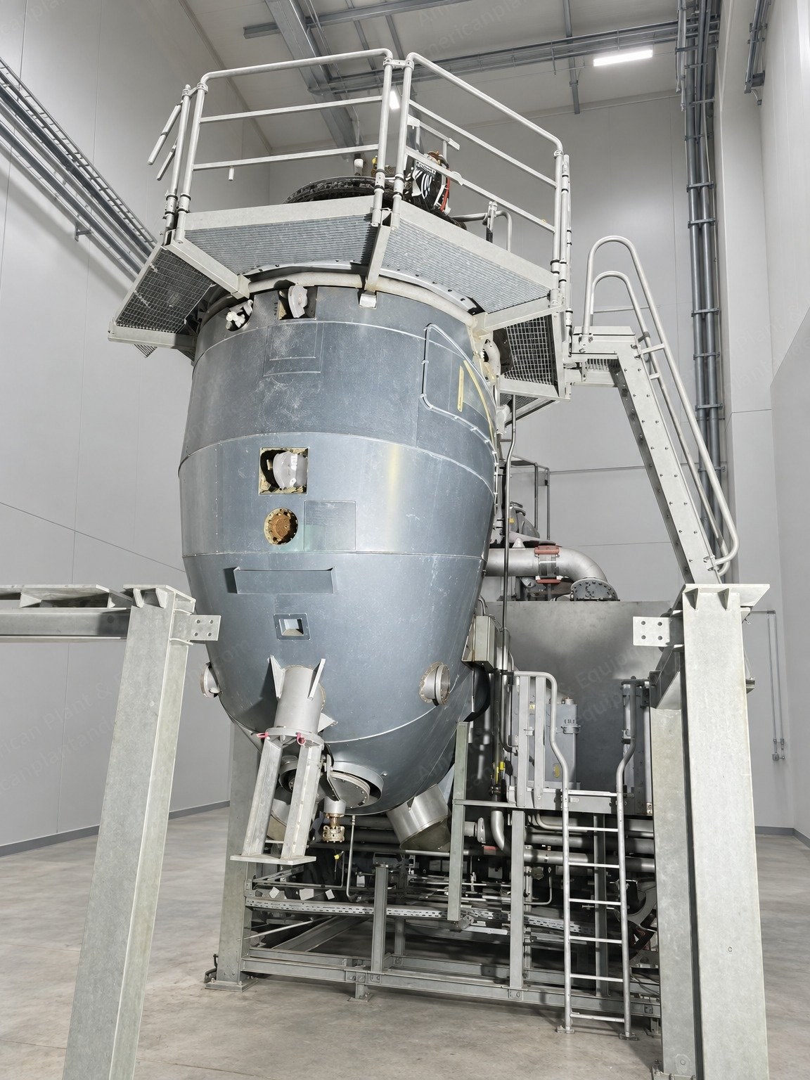
Siemens, SGT5-2000E, 2012, Combined Cycle Power Plant, 223.3 MW Each, 50 Hz, Natural Gas
Scroll to zoom
100%
Description
Overview
Siemens SGT5-2000E gas turbines in a combined cycle power plant configuration: natural gas-fired gas turbine with steam turbine and steam turbine alternator
Year: 2012
Quantity: 3 units
Hours: zero
Fuel: natural gas
Dry low emission
Assembly status: not fully assembled
Power and Electrical, Each Unit
Gas turbine power: 166 MW
Steam turbine power: 57.3 MW
Total power of each unit: 166 MW + 57.3 MW = 223.3 MW
HRSG high-pressure steam: 215.5 t/h at 7.05 MPag and 517.1 °C; maximum allowable working pressure 8.21 MPag
HRSG low-pressure steam: 46.5 t/h at 0.6 MPag and 214 °C; maximum allowable working pressure 0.896 MPag
HRSG inlet flue gas: 1,780.3 t/h at 538.2 °C and 5.394 kPa
Main power transformer: Siemens SFP-200000/220, 200 MVA, 50 Hz, YN,d11, ODAF cooling, manufactured September 2012
Main power transformer voltages: HV 242,000 V (taps 254,100-229,900 V), LV 18,000 V; LV current 6,415.0 A
Main power transformer weights: total 167,500 kg, oil 34,800 kg, transport 121,000 kg
Gas Turbine Package Documentation (Siemens SGT5-PAC 2000E)
Package documentation covers the gas turbine package: gas turbine, auxiliary and mechanical systems, electrical equipment (static excitation equipment SEE and static frequency converter SFC) and control system
Typical arrangement shown: SGT5-PAC 2000E gas turbine package for operation with natural gas as main fuel
Package documents: design conditions, media requirements, gas turbine island layout (plan view and section A-A), turbine control system configuration, gas turbine island electrical single line diagram, and large component transport list
Design Conditions: Plant Operation
Fuel type: natural gas
Start-up capable: yes; shutdown capable: yes
Load regime: base load
Maximum operating hours: 8,000 per year
Maximum starts: 40 per year
Design life, gas turbine: 100,000 equivalent operating hours (EOH) or 3,000 starts, whichever occurs first
Design Conditions: Electrical and Grid
Grid frequency, nominal: 50 Hz
Grid frequency range, continuous operation: 47.5-51.5 Hz
Grid frequency range, limited operation: 47.0-47.5 Hz and 51.5-52.0 Hz (maximum 20 seconds per occurrence and maximum 30 minutes accumulated)
Power factor, gas turbine generator: 0.85 lagging
Allowable generator voltage deviations with simultaneous grid frequency deviations based on IEC 60034-3
Primary frequency response (PFR) and secondary frequency response (SFR) operation considered, with the gas turbine heat-soaked, on fuel gas only, and with limited load gradient and load range
Grid sustaining fulfilled in principle; fault clearance times larger than 150 ms excluded; auto re-closing excluded
Load rejection to house load considered
Island operation at house load considered
Peak load (operation beyond base load): not provided
Design Conditions: Gas Turbine Load Gradients
Loading after grid connection: normal 11 MW/min, fast 15 MW/min
Unloading until grid disconnection: normal 11 MW/min
Load gradients valid per gas turbine between the initial load step after grid connection and 97% of rated power
Reference Design Conditions: Site and Environment
Site level: approximately 10 m above sea level
Indoor ambient air temperature: minimum 5 °C, maximum 45 °C
Outdoor ambient air temperature: minimum -14.9 °C, maximum 38.7 °C
Outdoor ambient air relative humidity: minimum 56%, maximum 68%
Outdoor ambient air absolute humidity: maximum 25 g/m3
Indoor arrangement of the equipment
Fuel Gas (Natural Gas at Terminal Point 14A)
Lower Wobbe index (LWI): design 48.2 MJ/m3 STP, permissible range 47.3-49.2 MJ/m3 STP
Pressure: minimum operational 22.12 bar(g) at 20 °C fuel temperature, maximum operational 31 bar(g), maximum design limit 31 bar(g)
Temperature: minimum 15 °C and dew point +28 K
Mass flow: maximum 12.90 kg/s
Pressure tolerance: ±5.0% of design value at 0-15% of maximum fuel flow, ±2.5% at 15-100%; change rate dp/dt ≤0.2 bar/s
Temperature permissible range: 5 °C to 60 °C (LHV 35.0-50.0 MJ/kg) or 5 °C to 120 °C (LHV 40.0-50.0 MJ/kg); tolerance ±10 K; change rate dT/dt ≤1 K/s
Condensation point: minimum 10 K above the dew point of the gas mixture and 15 K above the dew point of water
Lower heating value (LHV): design range 35.0-50.0 MJ/kg, tolerance ±5.0%, change rate ≤0.1%/s
Compressor cleaning: offline and online washing with de-ionized water
Lube and Hydraulic Oil
Lube oil: turbine oil ISO VG 46, kinematic viscosity 41.4-50.6 mm2/s at 40 °C, viscosity index ≥90, flash point >200 °C, pour point ≤-6 °C, aging ≥3,000 h
Turbine oil thermal stability: up to 110 °C in machine components and up to 80 °C in the oil tank
Hydraulic oil: grade HLP 46 per DIN 51524 Part 2 / ISO-L-HM 46 per ISO 6743-4, kinematic viscosity 41.4-50.6 mm2/s at 40 °C, flash point >185 °C, pour point ≤-15 °C, up to +70 °C in the hydraulic oil tank
Gas Turbine Island Equipment (per Layout Drawing)
Gas turbine
Generator for gas turbine
Base module, lube oil, with hydraulic skid, oil vapour extractor, hydraulic clearance optimization and fuel gas supply system
Enclosure for fuel gas system
Air intake filter house and duct, with transport box for filter elements
Exhaust gas system (diffuser)
Advanced compressor cleaning skid
Start-up unit transformer
Exciter transformer
Air dryer package
Noise protection walls for gas turbine and noise protection for combustion chambers
Enclosure for intermediate shaft
Generator neutral point cubicle
Generator current transformer terminal box
Shaft voltage and current measurement box
Local fire alarm panel
Space for generator rotor removal, monorail for bearing (2 t) and gas turbine rotor unloading / upending device
Electrical System (per Single Line Diagram)
Gas turbine generator: Siemens SGen5-100A-2, 15.75 kV ±5%, 50 Hz, cos φ = 0.85
110 kV grid connection via generator transformer
Generator circuit breaker and isolated phase busduct (IPB)
Gas turbine 10.5 kV unit switchgear, 3-phase 10.5 kV 50 Hz