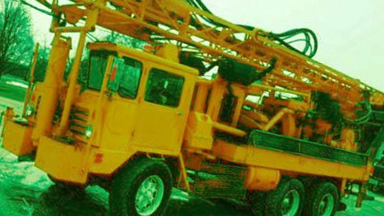
Portadrill, TG600, 1974, 30,000 lb Pulldown, Detroit 6V71 Deck Engine, Mounted on Crane Carrier

Description

  1. Overview
    1. Condition: Used
    2. Year manufactured: 1974
    3. Chicago pneumatic 650ws drill rig
    4. Noster tophead with 3” king swivel
    5. Atlas copco dt4 715/125 air compressors
    6. Failing 5 x 6 mud pump with pit
    7. 30,000# pulldown
    8. Double drum 2-part 5/8” drawworks for casing line/tophead with brakes
    9. Detroit 6v71 on deck
    10. Rod box and auto carry out with 11 pcs of 4-1/2” x 25’ pipe
    11. 20’ stabilizer
    12. (2) 8-1/2” roller cone bits, casing clamps
    13. Split breakout table with petol
    14. Cat triplex water injection
    15. 3” versa-matic diaphragm grout pump, 250 gal fuel
    16. Tool and block storage
    17. Mounted on crane carrier with henrickson suspension w/8.3l cummins
    18. 13 speed transmission
  2. Rotary Top Drive
    1. Rotary top drive updated to gearhead with king swivel.
    2. Powered by hydrostatic transmission system through double reduction chain drive to spiral ring gear and pinion with roller bearing supports.
    3. Spindle has 2-1/4” (57mm) i.d. air course with single neoprene packing ring and adjustable packing nut.
    4. Totally enclosed in steel case with oil bath lubrication.
    5. Original tophead included.
    6. Hydrostatic motor provides infinitely variable speed range from 0 to 145 rpm.
    7. Maximum torque to 4800-7500 ft. lbs. (57,600 in lbs.) is available at all speeds.
  3. Rotary Top Drive Hoist
    1. Heavy-duty mechanically operated hoisting drum is used to raise and lower top drive.
    2. Hoist provides 15,000 lbs. (6750 kg.) single line pull.
    3. Two-part 5/8” (15.9mm) non-rotating wire line. 30k
    4. Hoist speed range to 180 feet (54 m.) per minute using two-part line.
    5. Wrap-around cam-actuated 18” x 4” (457mm x 102mm) brake.
  4. Tool Handling Hoist
    1. 15,000 lbs. (6750 kg.) bare drum line pull.
    2. Single-line 9/16” (14.3mm) non-rotating wire line with safety hook.
    3. Wrap-around 18” x 4” (457mm x 102mm) cam-actuated brake. Now 2 part can be 3 or 4 part.
  5. Power Unit
    1. Engine and power divider connected as a unit.
    2. 6v-71n gm detroit diesel engine. 238 bhp at 2100 rpm
    3. Totally enclosed oil bath lubricated power divider transfer case. Power transferred through high speed chains running on heat treated sprockets.
    4. Low noise level exhaust silencers, two-stage dry-type air cleaner with service indicators. Large capacity for both engine and air compressor.
  6. Mast Assembly
    1. Electric welded high tensile strength seamless tubular steel construction.
    2. Two chrome-plated, double-acting, telescoping hydraulic cylinders with safety checks raise and lower mast.
    3. Drill stem rack is hydraulically positioned then locked for make up and racking of 2nd and 3rd stems. Na
    4. Rack holds stem securely when mast is in lowered transport position.
    5. Choice of three 30 ft. x 5-1/2. o.d. (9m x 140mm) or 30 ft. 4-1/2. o.d. (9m x 115mm) drill stems with double lead threads included. Na
  7. Pulldown
    1. Hydraulically powered pulldown with separate controls for rate of feed and down pressure driven through 2-speed transmission.
    2. Down pressure is infinitely adjustable to a maximum weight of 35,000 lbs. (15750 kg.) with ballast added.
    3. 2” (51mm) pitch roller chains, attached to top drive housing brackets, automatically feed full drill stem lengths.
    4. Feed rate adjustable. 0 to 6-1/2 feet (2.1 m.) per minute standard. Optional higher feed rates available.
  8. Air Supply
    1. Atlas copco dt4 two cylinder. Double-acting, air cooled, two-stage with a capacity of 715 cfm free air delivery at 55 psi; 675 cfm at 100 psi, 660 cfm at 125 psi (20.3 cu. m./min. at 3.9 kg./sq. cm., 19.1 cu. m./min. at 7 kg./sq. cm., 18.7 cu. m./min at 10.2 kg./sq. cm.) (based on 1180 rpm.)
    2. Driven through torque tube drive line from power transfer case. Air pressure unloading valve used to eliminate the need for a compressor crutch.
    3. Air cooled intercooler.
    4. Air receiver tank.
    5. Intake air filtered by oversized engine air cleaner.
  9. Water Injection System
    1. Duplex piston pump injects fluid into air line. Cat triplex
    2. Visual flow indicator.
    3. Hydraulically powered with infinitely variable speed control provides 0 to 8 gpm at 250 psi. (30 1. per min. at 17.6 kg./sq. cm) wash wand
    4. 250 gallon (950 l.) water reservoir. Na
  10. Dust And Cuttings Control
    1. Hydraulically driven type d. No. 8 roto-clone dynamic
    2. Precipitator draws dust and cuttings away from driller's area.

    3. Self-emptying skimmer precleaner removes larger cuttings.
    4. Roto-clone precipitator removes fine particles that are deposited into an air-tight hopper and allowed to settle before emptying.
    5. Adjustable, removable cuttings deflector hood surrounds drilled hole.
  11. Breakout System
    1. Rotary top drive reverses to break away from stem in rack or hole. Petol rig wrench
    2. Fork securely locks drill stem. Hydraulically powered
    3. Spanner type breakout pin is used for tools, bits and subs. Table is split to allow rear section to pull out.
  12. Hydraulic Leveling Jacks
    1. Single front jack with 48” (1220mm) stroke mounted on heavy-duty front bumper/mast cradle assembly.
    2. Two rear mounted jacks with 24” (610mm) stroke.
    3. Level indicator at driller's station.
    4. All outer tubes have locking pin holes.
  13. Instrumentation And Controls
    1. Instrument panel:
    2. Rotary top drive hydrostatic pressure gauge.
    3. Pulldown pressure gauge.
    4. Air pressure gauge.
    5. Compressor oil pressure gauge.
    6. Electrical system lock.
    7. Engine starter switch, oil pressure gauge, tachometer, water temperature gauge, ammeter, stop and emergency shutdown controls.
    8. Water injection flow indicator.
    9. Driller's station controls:
    10. Mast lift control.
    11. Water injection pump controls.
    12. Hydraulic jack controls.
    13. Top drive rotation control.
    14. Pulldown controls.
    15. Hydraulic breakout control and tong.
    16. Drawworks controls.
    17. Drill stem rack control. Auto carry out on rod bin
    18. Dust collector blower control. Na
    19. Rotary top drive hoist line brake.
    20. Engine throttle.
    21. Compressor unloader control.
    22. Tool handling hoist brake.
  14. Truck
    1. Heavy-duty, off highway tandem rear axle crane carrier corp. Truck chassis with half-cab.
    2. 501 cu.. displacement ihc gasoline engine powered.
    3. 8.3l cummins turbo diesel.
    4. 13-speed transmission.
    5. Wheelbase: 175” (4500mm)
    6. Front axle: 18,000 lbs. (8100 kg.) capacity with power steering.
    7. Tandem drive rear axle: 44,000 lbs. (19800 kg.) capacity.
    8. Solid rear suspension. Hendrickson rubber block/beam
    9. 15-22.5 16 pr front tires and 10.00 x 20 12 pr on/off highway tread rear tires.
    10. Air brakes with safety brake.
    11. Heater and defroster.
    12. Dot required equipment.
  15. Fluid Systems Capacities
    1. Hydraulic system reservoir: 80 gallons (304 l.)
    2. Hydrostatic system reservoir: 11 gallons (41.8 l.)
    3. Rig fuel tank: 85 gallons (323 l.) 300us gal
    4. Truck fuel tank: 40 gallons (152 l.) na
    5. Water tank: 250 gallons (950 l). Na
  16. Dimensions
    1. Length with mast down: 41 feet (12.5 m.)
    2. Length with mast up: 29-1/2 feet (9 m.)
    3. Height with down: 13 feet (4 m.)
    4. Height with up: 46 feet (14 m.)
    5. Width: 8 feet (2.4 m.)
  17. Weight
    1. Standard machine without tools, with mast down, approximate:
    2. Front axle; 13,450 lbs. (6052 kg.).
    3. Rear axle: 32,550 lbs. (14647 kg.).
    4. Total: 46,000 lbs. (20700 kg.)