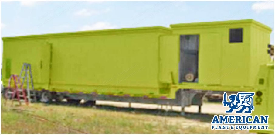
GE, TM2500, 2005, 22 MW, 60 Hz, Mobile Gas Turbine Unit
Scroll to zoom
100%
Description
Overview
Ge rebuild
Ge tm2500
Year of manufacture 2005
0 hours since overhaul
Output: 22 mw @ 60 hz (iso)
Full power in <10 minutes
Liquid or natural gas fuel capability
37.2% efficiency
Small footprint
Equipment Description And Scope Of Supply
The tm2500+ incorporates the lightweight lm2500+g4 aero derivative gas turbine with the brush 170er generator.
This is a modular system that consists of a main trailer, air filter trailer, exhaust silencer trailer, and an auxiliary trailer.
The main trailer contains a general electric turbine engine (model lm2500), switchgear, and an air-cooled generator connected through an engine-generator coupling.
The turbine engine is equipped to operate on natural gas or liquid fuel (dual fuel unit).
Main Trailer
Contains a general electric turbine engine (model lm2500), switchgear, and an air-cooled generator connected through an engine-generator coupling.
The turbine engine is equipped to operate on natural gas or liquid fuel (dual fuel unit).
Auxiliary Equipment Trailers
Supplied with the trailer mounted lm2500 set are three support trailers that contain the air filtration and exhaust equipment, fuel systems, lubricating systems, fire protection equipment, water wash, water injection, and fogging systems.
All interconnections between individual trailers are included.
These trailers are configured as follows.
Air Inlet Filter Trailer
Contains the combustion and ventilation air filtration equipment.
Includes high efficiency bag filters, ventilation fans and intake silencers.
Inlet ducting will have expansion capability to allow for additional silencing.
Exhaust Silencer Trailer
Contains the combustion exhaust silencer equipment, including an expansion joint, transition, silencer elbow, and stack with standard emission measurement ports.
Exhaust ducting will have expansion capability for additional silencing and have a flange designed for deflector assembly (deflector not included in scope).
Auxiliary Trailer
Contains the control house, lube oil cooler, hydraulic system, water wash system, water injection pumps, natural gas filter, and fire protection system.
Support System Equipment
The packaging of the trailer mounted lm2500 set includes a turbine generator control panel (tcp), digital generator protection relay system, 400v motor control centre (mcc), and 24 and 125v dc battery systems, including battery racks and chargers.
This equipment is contained in the control house, located on the auxiliary trailer.
Turbine-Generator Control System
The turbine-generator control and monitoring system regulate the lubrication, fuel supply, ventilation and cooling, fire safety, and maintenance functions.
Fuel supply is regulated by a computerised fuel control and sequencer system.
The control system monitors all operating systems and initiates alarms and shutdowns when hazardous conditions occur.
Manual emergency shutdowns can be initiated with emergency stop buttons located on the exterior of the main and auxiliary trailers, as well as at the tcp.
The control system is expandable to accept additional inputs, alarms, etc.
Terminal Points
Combustion air: inlet face to air inlet filter house
Exhaust: exit from the gas turbine exhaust stack
Fuel: inlet flange to the gas turbine on base fuel system (fuel to be supplied clean filtered and compliant to pratt and whitney specifications)
Cooling system: water filling connection on the fin-fan cooler header tank
Lube oil: make up flange connection on the gas turbine on-base reservoir
Ventilation: inlet/outlet grilles on unit enclosure
Drains and vents: on-base flange/connections lube oil vent outlets, gas vent outlets
Electrical (hv): high voltage outgoing terminals of high voltage switch (voltage to be confirmed once know and transformers ordered accordingly)
Electrical (lv): lv power terminals on the auto-changer panel standby supply and junction box (external interfaces by others)
Control system: control terminals on each junction box for external interfaces by others
Earth grid: earthing points located on and around equipment skids
Request a Quote
✓
Request sent
Thank you, our team will reply to you shortly.
Direct access to our team
Email American Plant & Equipment
Tell us what you want to buy, source, finance, or sell. A machinery specialist will follow up with you.
✓
Thank you. Your request is with the American Plant and Equipment team.
A machinery specialist will follow up with you.
Machinery updates
Subscribe to our email list
Tell us which industries you follow and we will send you the machines that match.
✓
You are on the list.
We will email you when machines that match your interests come in. Unsubscribe from any message.