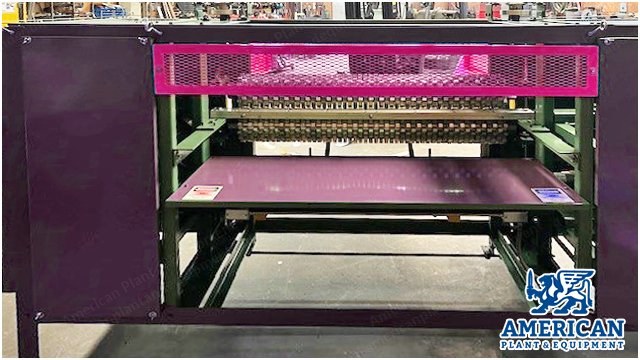
Convoluter, 48" Working Width, 2023, 6" Max Thickness, Bandknife Cutting
Scroll to zoom
100%
Description
Overview
Convoluter
Almost new condition
Working width: 48 in
Year: 6/2023
Capacity: This machine will accept flexible polyurethane foam sheets of suitable quality up to six inches thick and unlimited length.
Cutting Assembly
The bandknife, 1 1/2 in wide, runs on two rubber tired, ball bearing mounted wheels, powered by electric motor and belt drive.
Rigid, machined knife guide bar supports the blade at the cutting position.
Bar equipped with adjustable and replaceable backstop.
Knife blade take-up wheel adjustable for knife tracking.
Safety control will stop the machine if the knife breaks.
Forming Rolls
Precisely machined cast aluminum or pattern dies are mounted on steel rolls.
Standard pattern two inches from point to point.
Rolls are ball bearing mounted and removable.
Depth controlled by handwheel powered adjusting lead screws.
Rotary and/or linear scales indicate the amount of compression.
Roll Drive
Pattern rolls powered by electric motor and gear drive via universal joints.
For added safety and easy roll removal and aligning of pattern, split compression couplings are incorporated in the drive assembly.
Material Handling
Table, adjustable for height requirements for different thickness of foam sheets, mounted in front of the cutting position.
Stationary table or optional take-away conveyor, located in rear of the machine.
Guards
This machine is covered with removable steel panels.
In front of the cutting area expanded metal cage guard covers the feed-in part of the machine.
Removal of this guard will shut off the power.
Grinders
The knife assembly equipped with continuous duty sharpeners, powered by two 1/4 hp electric motors.
Handwheel adjustments for horizontal and vertical movements for the grinders.
Electrical
All motors 3/230-460/60 hz, totally enclosed.
Wiring emt and rubber cable.
Magnetic starters with overload relays.
Magnet coils line voltage.
Enclosures nema 1.
Wall disconnect provided by user.
Controls
The first 2 buttons start the blade.
The speed control under it controls the blade speed.
The next 2 buttons turn the feed rollers on.
The speed controller under it controls the feed roller speed.
The next switch controls the direction of the feed roller: forward to feed material, reverse to back the material out of the machine.
The grinder buttons will power on the grinders.
Top Roller Adjustment
The numbers on the round dial are for fine tuning.
You have a ruler on a scale to get your setting close.
Bottom Roller Adjustment
The bottom roller numbered dial is for fine tuning.
You have a ruler to get it close.
Table Adjustment
This ruler is for the table height.
Blade Sharpener
You have the ability to move the sharpeners up and down on both motors.
Blade Sharpening
The grinders are set here at the shop.
Turn the handle counter clockwise to move the grinders.
Turn the handle clockwise to move them out.
Convoluter Operation
Check the work area to make sure it is free of obstruction and debris.
Turn main disconnect on the control cabinet to the on position.
Pull the e-stop button out.
Adjust the table height to fit the thickness of the foam. This is done by hand wheels under the table.
Adjust the rollers for the thickness of the material and the convolution required. The rollers are adjusted independently by hand wheels on the front right side of the machine to obtain proper peak and base thickness. The scales and pointers are provided for the measurement from the rollers to the blade.
Start the blade with the start blade button. Flashing light will come on. The blade speed can be controlled with the speed pod on the machine. The blade will not start if any of the following conditions exist: safety cable is pulled, e-stop is pushed, blade break switch is tripped.
Note: Do not adjust the blade speed or rollers when motors not running.
Start the rollers by pushing roller start button. The rollers will not start if any of the following: safety cable is pulled, e-stop is pushed, blade break switch is tripped, blade motor is not running.
Note: The rollers have a forward/reverse switch. If you have a hang up you can reverse the roller to clear the jam.
Adjust the roller speed to get the best cutting performance of the material.
Start the blade grinder, the blade must be running. The grinder wheels can be adjusted up and down by way of hand wheels inside the bottom right cabinet. The grinder can also be moved in and out by way of the hand wheel outside of the bottom right cabinet. The grinder will be set at our shop in the up/down position. You will need to move them in to sharpen blade.
Note: Once the blade is sharp you will need to buff the blade some as you make cuts. Do not hard sharpen if the blade is sharp.
Note: Excessive grinding may cause the blade to heat up and move out of the blade guide.
Note: Blade must be kept sharp to prevent binding of material in rollers.
Maintenance Instruction
Components requiring special maintenance are covered herein. Items not specifically covered require no special care, other than generally given any piece of industrial equipment.
Abuse and dirt are the chief enemies of any piece of equipment. If the equipment is kept clean and not abused, it will give satisfactory operation within the limit of its specifications.
These instructions do not purport to cover all details or variation in equipment or to provide for every possible situation to be met in connection with installation, operation, or maintenance.
Turn power off at the main disconnect before doing any maintenance on this machine.
Installing the Blade
Blade installation is done from the back side of the machine (exit side). The blade is fed in and laid in place, then from the front access panels the blade can be placed onto the wheels and fitted into the blade guide and the grinder block.
Adjusting the Blade Tension
The idler wheel has the blade tension adjustment. Adjust the blade so the red round plate makes the limit switch. This is preset at the shop.
After blade is installed, close doors and run the blade a couple of minutes. Stop blade. Guide should be cool to the touch.
Adjusting the Rollers
The rollers are parallel with each other as well as the stripper guide and blade.
Rollers are also aligned with each other so the center line of each roller is in line with the other.
Note: Rollers are preloaded last 3/8 of travel from the blade.
The adjustments referred to in the above paragraphs, as well as the centerlines of each roller, should be maintained by the operator. Periodic checking of the bearing bolts will keep the centerline parallel. Should this arrangement move by vibration or come loose at the bearing mounts realign the rollers.
After moving the rollers to align centerlines, you should check the parallel of the two rollers in relation to themselves and the stripper guide and blade. Once these settings are made, a periodic check should suffice.
Should you wish to raise or lower one end of the rollers independently of the other end, loosen set screw in the small bevel gear on the shaft, move it off the big bevel gear and turn the big bevel gear to raise and lower the roller.
The foot of the convoluting ring of the upper roll must be in line with the space between two feet on the corresponding roll below. A slip coupling is found on each end of the rollers. Loosen the 4.
Request a Quote
✓
Request sent
Thank you, our team will reply to you shortly.
Direct access to our team
Email American Plant & Equipment
Tell us what you want to buy, source, finance, or sell. A machinery specialist will follow up with you.
✓
Thank you. Your request is with the American Plant and Equipment team.
A machinery specialist will follow up with you.
Machinery updates
Subscribe to our email list
Tell us which industries you follow and we will send you the machines that match.
✓
You are on the list.
We will email you when machines that match your interests come in. Unsubscribe from any message.