
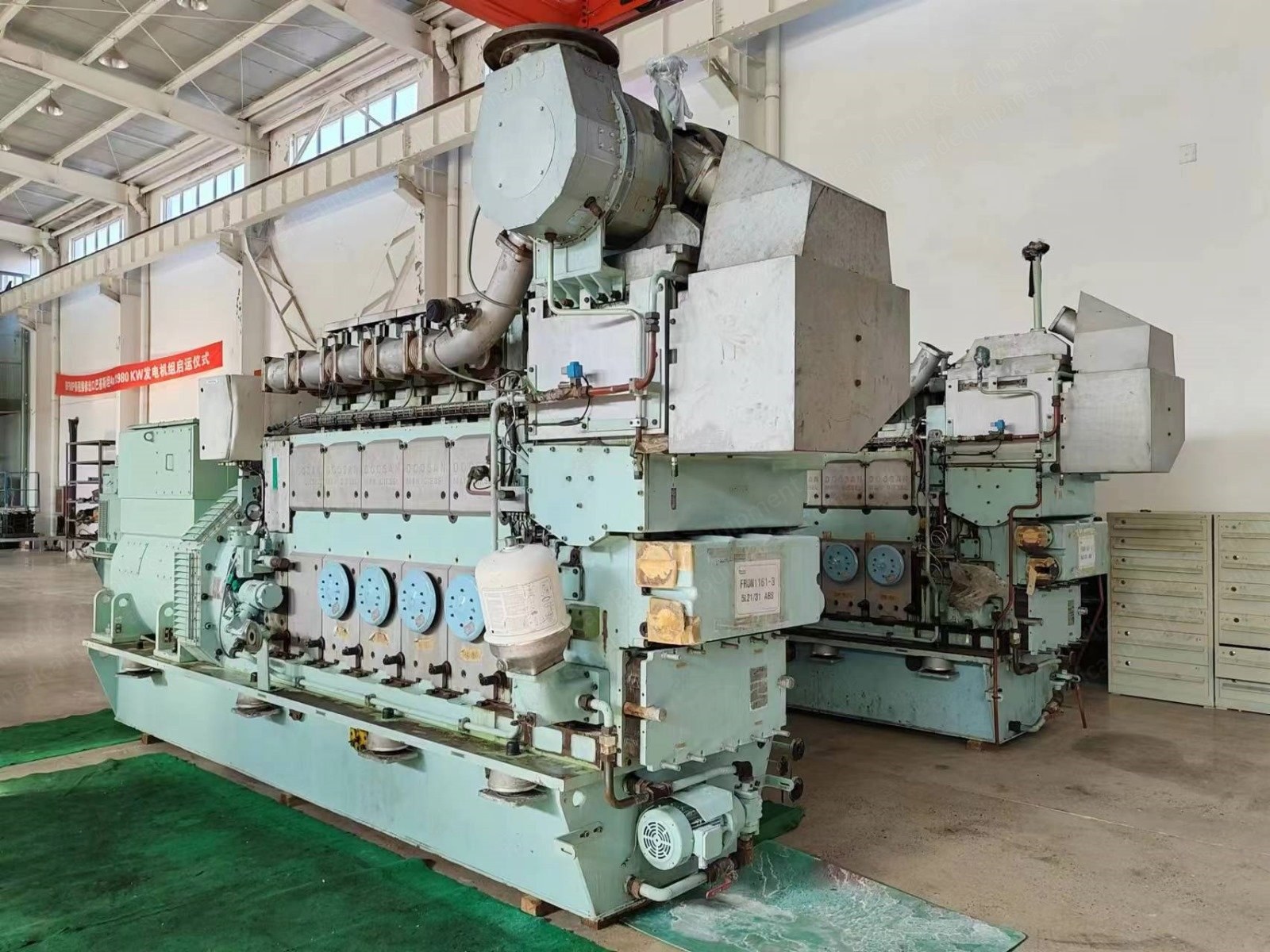
Description
STX-MAN Diesel Generator Set, Model 8L27/38, Power Output 2640 kW (2500 kW continuous)
1. General Principles
1.1 General Description
- Project: Power Station Project
- Stock new unit: 8L27/38 main generator set
- Quantity: 4 × 8L27/38 units
1.2 Design Standard
All related standards comply with the latest versions. The equipment is supplied according to:
- ISO standard / GB standard
- IEC standard
- MAN standard
- Manufacturer’s own standard
1.3 Design Operation Environment
- SO environment conditions
1.4 Unit and Language
- Technical documents and drawings include values in MPa/bar for pressure and °C for temperature.
2. Gen-Sets Main Performance Parameters
2.1 Technical Specification of Gen-Sets
Table 1: Nominal Maximum Continuous Rating
Item | Parameter | Value |
|---|---|---|
1 | Engine Speed | 720 rpm |
2 | Output Power (MCR) | 2640 kW (≈ 3540 HP) |
3 | Continuous Operation Power | 2500 kW (≈ 3352 HP) |
4 | Frequency | 60 Hz |
5 | Voltage | 450 V |
6 | Power Factor (lagging) | 0.8 |
7 | Atmospheric Pressure (reference) | 1000 mbar (≈ 14.5 psi) |
8 | Cooling Water Temperature (before air cooler, reference) | 25 °C (77 °F) |
9 | Ambient Temperature (reference) | 25 °C (77 °F) |
10 | Relative Humidity (reference) | 30% |
2.1.2 Diesel Engine Generator Mounting
- The diesel engine and generator are rigidly coupled and mounted on a common base frame.
- The base frame is resiliently mounted against the foundation.
2.1.3 Gen-Sets Nameplate
- Material: Brass
- Language: English
2.2 General Information of Engine
- Engine Type: STXMAN 8L27/38
- Cycle/Configuration: Four-stroke, inline, 8 cylinders
- Bore/Stroke: 270 mm (10.63) / 380 mm (14.96)
- Air Intake: Turbocharged and intercooled
- Rated Power/Speed: 2640 kW at 720 rpm
- Crankshaft Rotation: Clockwise (viewed from flywheel)
- Air Intake Vacuum Requirement: ≤ 2.5 kPa (≤ 0.36 psi) at rated condition
- Exhaust Back Pressure: ≤ 2.5 kPa (≤ 0.36 psi) at rated condition
- Fuel Designation: MDO/HFO (HFO must satisfy ≤ 380 cSt/50 °C (122 °F))
- Fuel Consumption (at rated condition): 195 ± 5% g/kWh (not including engine-driven pump)
- Lube Oil Specification: SAE CF40 or better
- Lube Oil Consumption (MCR condition): 0.8 g/kWh
- Cooling Water Additives:
- The cooling water must include anti-corrosion and anti-cavitation additives.
- Indices of the treated cooling water must conform to the diesel engine manufacturer’s specification.
2.3 General Information of Alternator
- Model: HFJ7 718-14K
- Manufacturer: HYUNDAI
- Capacity: 3125 kVA
- Voltage: 450 V
- Protection Degree: IP44
- Ambient Temperature (rated): 50 °C (122 °F)
- Rated Speed: 720 rpm
- Frequency: 60 Hz
- Power Factor: 0.8
- Connection/Rating: Y / Continuous
- Insulation Class: F
2.4 Rated Ambient Condition of Diesel Engine
- Atmospheric Pressure: 100 kPa (≈ 14.5 psi)
- Air Pressure: 60% (Note: original text unclear, possibly referring to relative humidity or partial pressure.)
- Air Relative Humidity: 45 °C
- Environment Temperature: 32 °C (89.6 °F)
- Seawater Temperature: (Not fully specified in the text; user note.)
If actual ambient conditions differ from the above, the power and consumption must be adjusted according to the manufacturer’s standard.
2.5 Engine Overall Dimension and Weight
Table 2: Engine & Generator Set Dimensions and Weight
Item | Parameter | Dimension |
|---|---|---|
1 | A | 5681 mm (223.7) |
2 | B | 2986 mm (117.6) |
3 | C | 8667 mm (341.3) |
4 | H | 3717 mm (146.3) |
5 | Dry Weight (Gen-Set) | 56.5 t (≈ 124,560 lb) |
3. Generator Set Main Equipment Composition
(Scope of supply for each machine)
3.1 Basic Composition
- Body assembly, front box, back-end cover, oil pan, driving mechanism, cylinders, etc.
3.2 Fuel System
Standard Supply
- Injection pump, high-pressure pipe, injection valve for each cylinder
- Leakage alarm box for leaking oil, LAH42
3.3 Lubrication System
Standard Supply
- Wet oil sump (in base frame)
- Engine-driven lubricating oil pump
- Plate-type lubricating oil cooler (stainless steel)
- Electrically driven pre-lubricating pump
- Duplex filter
- Thermostatic 3-way valve
- Lubricating oil centrifugal by-pass filter
- Lubricating oil viscosity requirement: SAE 40 CD class
- Connection for lubricating oil to/from separator
- Lubrication oil overflow connection
3.4 Cooling Water System
Standard Supply
- HT (high-temperature) and LT (low-temperature) cooling water system (two-string type)
- Engine-driven H.T. water pump
- Engine-driven L.T. water pump
- Thermostatic 3-way valve (for H.T. water system)
- Thermostatic 3-way valve (for L.T. water system)
3.5 Compressed Air System
Standard Supply
- DC 24 V solenoid valve for local/remote start and emergency start valve
- Air starter for engine starting, max. working pressure 1.0 MPa (≈ 145 psi)
- Reduced pressure valve set (includes safety valve, filter, and pressure gauge), 1 set/engine—loosely supplied; the owner must supply up to 3.0 MPa (≈ 435 psi) compressed air. (Not included, optional)
- Electric turning motor
3.6 Combustion Air System
Standard Supply
- Turbocharger
- Charge air cooler
- Water washing connection for turbocharger compressor
3.7 Exhaust Gas System
Standard Supply
- Gas outlet for vertical pipe connection (after turbocharger)
- Dry cleaning connection for turbocharger turbine
- Exhaust bellows between cylinder and exhaust pipe (with heat insulation cover), and between cylinder and turbocharger
3.8 Governor System
- Governor Type: Mechanical hydraulic governor (electronically controlled)
3.9 Control and Monitoring System
Standard Supply
- Alarm and shutdown sensors in accordance with classification society standard and MAN standard
- MAN control system, including:
- Control module (for engine control, monitoring, and alarm)
- Indication module (for displaying engine and safety system data)
- Safety shutdown system for:
- Overspeed
- Low lubricating oil pressure
- High cooling water temperature
- Emergency stop
- Note: Owner must supply two-way (redundant) DC 24 V uninterrupted power sources.
3.10 Alternator
Standard Supply
- Model: HFJ7 718-14K
- Brand: HYUNDAI
- Voltage: 450 V
- Frequency: 60 Hz
- Power Factor: 0.8
- Protection Class: IP44
- Insulation Class: F
4. Standard Spare Parts (Not Included, Optional)
Below is the spare parts list for Generator Sets 8L27/38 (optional supply, not included by default).
Table 3: Standard Spare Parts
Item | Name | Unit | Qty |
|---|---|---|---|
1 | Main bearing shell-lower | Piece | 1 |
2 | Main bearing shell-upper | Piece | 1 |
3 | Thrust ring | Piece | 2 |
4 | Bearing bush camshaft INJ | Piece | 1 |
5 | Bearing bush camshaft valve | Piece | 1 |
6 | O-Ring | Piece | 1 |
7 | O-Ring | Piece | 1 |
8 | O-Ring | Piece | 1 |
9 | O-Ring | Piece | 1 |
10 | Cyl liner | Piece | 2 |
11 | Frame step ring | Piece | 1 |
12 | Sealing ring for cyl liner | Piece | 1 |
13 | O-Ring | Piece | 1 |
14 | O-Ring | Piece | 1 |
15 | O-Ring | Piece | 1 |
16 | Sealing ring | Piece | 1 |
17 | Connecting rod | Piece | 1 |
18 | Connecting rod bearing | Piece | 1 |
19 | Connecting rod bearing | Piece | 1 |
20 | ASSM. Piston | Piece | 1 |
21 | Piston pin | Piece | 1 |
22 | Retaining ring f.borings | Piece | 2 |
23 | Compression ring | Piece | 1 |
24 | Compression ring | Piece | 1 |
25 | Oil scraper ring | Piece | 1 |
26 | Cylinder head with valves | Piece | 1 |
27 | P-ring viton | Piece | 1 |
28 | Gasket | Piece | 1 |
29 | O-Ring | Piece | 1 |
30 | O-Ring | Piece | 1 |
31 | Inlet valve cone | Piece | 4 |
32 | Valve cone exhaust | Piece | 4 |
33 | O-Ring | Piece | n |
34 | Press spring | Piece | n |
35 | Valve rotating device | Piece | 4 |
36 | Valve cone piece | Piece | 4 |
37 | Indicator valve | Piece | 1 |
38 | Safety valve | Piece | 1 |
39 | Gasket | Piece | 1 |
40 | O-Ring | Piece | 4 |
41 | F.O. injection pump | Piece | 1 |
42 | Connection pipe (lance) | Piece | 1 |
43 | Ring | Piece | 1 |
44 | Round seal ring | Piece | 1 |
45 | Fuel injection pipe | Piece | 1 |
46 | O-Ring | Piece | 2 |
47 | ASSM. fuel injection valve | Piece | n |
48 | O-Ring | Piece | n |
49 | O-Ring | Piece | n |
50 | O-Ring | Set | 1 |
5. List of Standard Tools (Not Included, Optional)
Table 4: Standard Tools
Item | Name | Part No. | Qty |
|---|---|---|---|
1 | Valve spring tightening device | 52000-014 | 1 |
2 | Cylinder head spreader | 52000-038 | 1 |
3 | Removal device for fire band ring | 52000-021 | 1 |
4 | Guide for piston | 52000-045 | 1 |
5 | Install/remove device for connecting rod bearing | 52000-069 | - |
6 | Cylinder liner lifting device | 52000-082 | 1 |
7 | Piston lifting device | 52000-104 | 1 |
8 | Piston ring opener | 52000-190 | 1 |
9 | Piston connecting rod cylinder liner installation tool | 52000-212 | 1 |
10 | Feeler gauge | 52000-010 | 1 |
11 | Valve clearance adjustment tool | 52000-652 | 1 |
12 | Indicator valve handle | 52002-498 | 1 |
13 | Spindle tile (upper tile) removal tool | 52000-035 | 1 |
14 | Marine fixing tool | 52000-060 | 1 |
15 | Ring screw | 52000-036 | 1 |
16 | Dry cleaning gun | 51210-136 | 1 |
QUANTITY available: 1