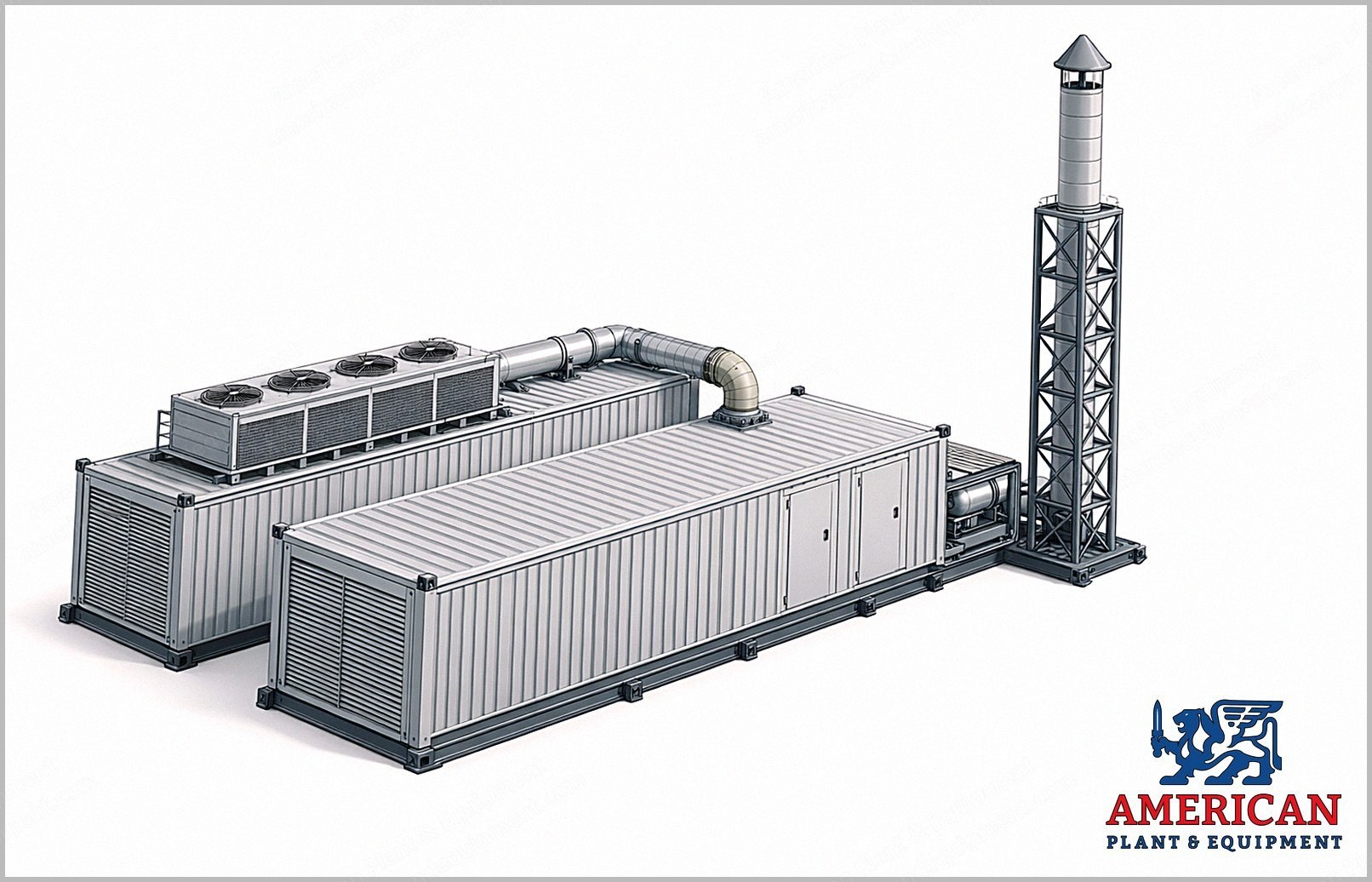
Complete outdoor modular cogeneration plant built around a Jenbacher Series 6 gas engine of the JGS 616 type.
Plant model designation ECOMAX 27 HE, outdoor modular solution.
Rated electrical output of the module is 2,681 kW per the plant technical specification.
Electrical equipment in the specification is rated at 50 Hz.
Two heat recovery circuits are provided: saturated steam raised from the exhaust gas in a waste heat boiler, and hot water recovered from the engine cooling circuit and the residual exhaust heat.
Exhaust gas is treated by a urea SCR system followed by an oxidation catalyst.
The plant is housed in two purpose built outdoor steel enclosures, one for the cogeneration module and one for the auxiliary services.
The seller reports the plant is in excellent condition, has run only a small number of hours, and has at least 50,000 hours of service life remaining. It is available for inspection.
The description below is taken from the original technical specification issued with this plant and describes it as originally built.
The exact scope of supply for resale is to be confirmed.
Design and Reference Conditions
Residual noise level in free field without acoustic reflection 70 dB(A) at 10 m (33 ft).
Design ambient temperature plus 25 C (77 F).
Maximum ambient temperature plus 35 C (95 F).
Height of the exhaust gas stack discharge above ground 13 m (43 ft).
Island operation and black start were not part of the original design.
Exhaust Emissions with the Urea Treatment System
NOx at 5 percent O2 less than 75 mg/Nm3.
NH3 at 5 percent O2 less than 5 mg/Nm3.
CO at 5 percent O2 less than 100 mg/Nm3.
Enclosures, Ventilation and Acoustic Insulation
Two purpose built carbon steel structures for outdoor installation, each approximately 14,020 x 2,990 x 3,320 mm (L x D x H) (552 x 118 x 131 in), on base frames carrying everything inside, clad in electro galvanized corrugated sheet, with corner blocks for crane lifting and a RAL 7035 grey polyurethane finish.
Module enclosure with an oil tight tray type floor to contain accidental lubricant spills, and walls and ceiling acoustically insulated with rock wool panels faced in perforated sheet.
Air inlet plenum at the alternator end and an extraction plenum opposite, with galvanized steel acoustic splitters, weatherproof grilles with bird mesh, inlet filter cells, motorized extraction dampers and inlet fans.
Services enclosure divided into rooms with access doors, normal and emergency lighting and an air conditioner for the control room, housing the electrical equipment, the hydraulic components, the circulating pumps and the oil top up system.
A third purpose built carbon steel structure for outdoor installation, approximately 7,000 x 2,990 x 3,320 mm (276 x 118 x 131 in), of the same construction and finish, ventilated and lit and fitted with medium voltage cabin accessories, housing the medium voltage cogeneration switchboard, the QLA panel and the auxiliary services transformer, with the urea storage for the SCR system in a separate room inside it. It formed part of the original installation; its inclusion in the resale is to be confirmed.
Mechanical Equipment
Seamless carbon steel pipework with welded joints for the heat recovery and dissipation circuits, with circulating pumps, expansion vessels, three way control valves and instrumentation, insulated in rock wool clad in aluminium sheet.
Plate heat exchanger on the engine circuit, decoupling the secondary heat recovery circuit; second stage intercooler circuit run to its own emergency cooler.
Emergency electric cooler on the enclosure roof, with fans, painted galvanized steel casing, copper tubes and aluminium fins.
Natural gas line with manual and servo actuated safety shut off valves, the run to the engine gas ramp and the gas ramp itself, plus an ATEX certified flameproof gas shut off valve.
Automatic lubricating oil top up system with two 1,000 litre (264.2 gal) (264 US gal) tanks for fresh and used oil over a welded steel collection tray, and an exhaust silencer sized for the reference noise level.
Exhaust Gas Line
AISI 304 stainless steel exhaust line from the engine to the urea SCR system, to the waste heat boiler with its bypass circuit, to the silencer and to the stack, with expansion joints and a sampling point on a service walkway.
Bypass circuit with interlocked damper type diverter valves under modulating actuator, a condensate collection system with a drum tank, and an AISI 304 stack with conical cap on a galvanized steel support structure.
Exhaust line externally insulated.
Waste Heat Boiler for Steam Production
Horizontal fire tube heat recovery unit producing saturated steam from the exhaust gas, externally insulated with mineral wool clad in aluminium sheet, built to European Directive 97/23/EC (PED).
Fitted with ECO 1 on the steam circuit and ECO 2 on the hot water circuit as additional heat recovery stages, and served by a vertical cylindrical carbon steel flash tank with instrumentation on the condensate return from the cogeneration package.
Design data: flue gas flow 14,576 kg/h (32,134 lb/h), flue gas inlet temperature 383 C (721 F), flue gas outlet temperature 120 C (248 F), boiler design temperature 535 C (995 F).
Operating data net of radiation losses: boiler output 811 kW (1,087.6 hp), ECO 1 output 131 kW (175.7 hp), ECO 2 output 226 kW (303.1 hp), saturated steam production 1,418 kg/h (3,126 lb/h), feed water temperature 93 C (199 F), operating temperature 187.96 C (370 F), operating pressure 11 barg (160 psig), design pressure 15 barg (218 psig), hydraulic test pressure 21.5 barg (312 psig).
Exhaust Gas Treatment by Urea SCR
Selective catalytic reduction of nitrogen oxides with a technical urea solution: the solution is dosed, atomized with compressed air, injected into the exhaust stream, mixed by static mixers in the duct and reduced over a catalyst to water and nitrogen.
A ceramic honeycomb oxidation catalyst downstream cuts carbon monoxide, unburned non methane hydrocarbons and residual ammonia, and a pre oxidation unit sits upstream.
Urea storage in a separate room inside the third outdoor structure, with a 2,000 litre (528.3 gal) (528 US gal) tank, feed pump and pipework.
Components and exhaust line insulated in ceramic fibre and rock wool clad in aluminium sheet.
Electrical Equipment and Controls
Group auxiliary control panel QCG100 of the Complex type, with a PLC based automatic auxiliary management system that handles the module common functions and the grid interface, acquires every engine signal and controls the auxiliaries; the main safety signals are hard wired.
Automatic synchronizing equipment for paralleling with the utility grid, and inverter control of enclosure ventilation and of the module emergency heat dissipation.
Parameters acquired include alternator breaker status, engine cooling water and oil temperature and pressure, mean and individual cylinder exhaust temperatures, return water temperature, number of starts, speed, and alternator power factor, frequency, currents, line voltages and active, reactive and apparent power.
Fire and gas detection with point type smoke detectors, a gas sensor near the engine gas ramp and a detection and alarm control unit, all processed by the plant PLC.
The Siemens PLC control logic and the supervision graphics are included.
Medium voltage fit out of the module: alternator star point cell, UTF metering cell, surge arresters, and three phase connections in RG7H1R 12/20 kV cable with preformed terminations.
Request a Quote
✓
Request sent
Thank you, our team will reply to you shortly.
Direct access to our team
Email American Plant & Equipment
Tell us what you want to buy, source, finance, or sell. A machinery specialist will follow up with you.
✓
Thank you. Your request is with the American Plant and Equipment team.
A machinery specialist will follow up with you.
Machinery updates
Subscribe to our email list
Tell us which industries you follow and we will send you the machines that match.
✓
You are on the list.
We will email you when machines that match your interests come in. Unsubscribe from any message.