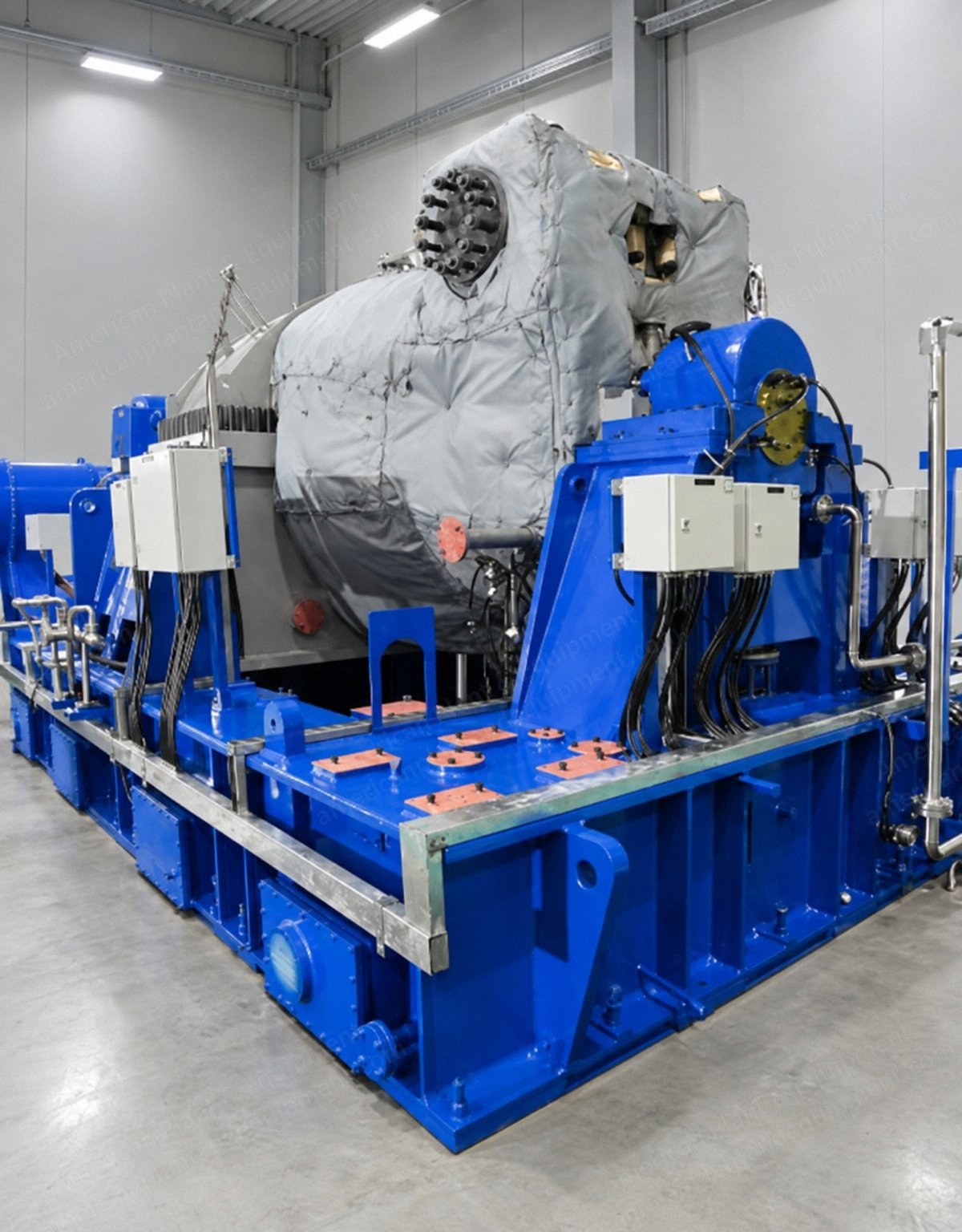
Description OverviewNew-build back pressure steam turbine generator set, multi-stage reaction turbine with reduction gearbox and synchronous generatorElectrical output: 9,270 kW (12,431 hp) at design steam conditions, 60 HzSized to use the full available steam flow of 68,000 kg/hr (149,914 lb/hr)Built to orderTurbine Design Operating ParametersSteam inlet pressure: 36 ata (512 psia)Steam inlet condition: superheatedSteam inlet temperature: 400 °C (752 °F)Steam inlet flow rate: 68,000 kg/hr (149,914 lb/hr)Steam exhaust pressure: 2.5 ata (35.6 psia)Steam exhaust temperature: 127.41 °C (261.3 °F)Steam exhaust flow rate: 68,000 kg/hr (149,914 lb/hr)Electrical power: 9,270 kWSpecific steam rate: 7.335 kg/kWh (16.17 lb/kWh)Steam TurbineMulti-stage, reactionOperating speed: approximately 9,800 rpmGland seal: labyrinthBlades: X22 Cr.Mo.V.12-1Nozzles: X22 Cr.Mo.V.12-1Rotor shaft: 30 Cr.Mo.Ni.V.5-11Diaphragm: X22 Cr.Mo.V.12-1Casing: G17 Cr.Mo.5-5Steam chest and emergency stop valve: G17 Cr.Mo.5-5Bearing housing: G18 Mo.5Pedestal: structural steel, grade E275 BRLabyrinth seals: 'J' wire labyrinthMild steel base frame, common for turbine and gearboxTilting pad journal and thrust bearings, white metal on steel (Michell)Design standards: IEC 60045, ASME, ASTMSynchronous GeneratorHigh voltage, 9,270 kWAC, three phase, 4-pole, 60 HzVoltage to be specified by the buyerIP54 protectionClass F insulation, temperature rise limited to Class BClosed air circuit, water cooled (CACW)Maximum working ambient temperature: 45 °C (113 °F)GearboxRated power: 9,270 kWeHelical, single stage reduction gearbox with barring gearMinimum service factor of 1.3 (rated for short circuit torque in 2 phase and 3 phase)Design standard: AGMA 6011ActuatorVoith (Germany), electro-hydraulicSingle acting hydraulic cylinder, extendable by springWay valve with cartridge valve (if necessary)Stroke electrically adjustable by analog signal with potentiometerServomotor clevis mounted, vertical orientation (rod upwards)Emergency Stop ValveSpring loaded, hydraulicRedundant trip solenoids (SIL2 safety rating each, resulting in SIL3)CouplingsNon-lubricated, steel laminated, flexible couplings between turbine and gearbox and between gearbox and generator, with coupling guardsLubrication SystemForce-feed lubrication systemLube oil tank with cleaning doors and breatherMain oil pump driven by the gearbox low speed shaft (Rickmeier, Germany, or equivalent)415 V AC three phase motor driven auxiliary oil pump with automatic cut-in and cut-out110 V DC motor driven emergency oil pumpSuction strainers for the main, auxiliary and emergency oil pumpsPressure regulating valvesTwin oil coolers with RTDs for temperature measurementTwin oil filters, 16 micronAssociated piping, pressure gauges and other valvesGland Steam CondenserShell and tube type with exhaust fanControl Panels and InstrumentationPLC turbine control panel (Siemens, Rockwell or equivalent)Generator control panel (relays, metering and synchronizing panel)Neutral grounding resistor (NGR) panelLightning arrester, surge capacitor and voltage transformer (LA/SC/VT) panelAVR / excitation panel (ABB Unitrol)Turbine generator motor control center with AC distribution boardDC motor starter panelVibration monitoring system: housing sensors on the low speed train, shaft sensors on the high speed trainDedicated overspeed protection system (Heinzmann / Woodward, 2 out of 3)AccessoriesFoundation bolts and leveling blocks / wedgesPerformance NotesPerformance data applies at steady state conditions, with the control valve fully open and deposit free bladingElectrical power is guaranteed when the turbine is operated at design parameters onlyPerformance data does not include the power and steam requirements of auxiliary equipmentTolerance of plus or minus 3% applies to the power outputUtilities Required at Site (Indicative)Clean, dry instrument air: 5 SCFM at 7 kg/cm2 g (100 psig)Cooling water: 4,000 L/min (1,057 US gpm) at 28 °C (82 °F) and 2.5 kg/cm2 g (36 psig)Continuous three phase, low voltage, 50 Hz AC auxiliary power supplyContinuous 110 V DC power supplyNot IncludedSteam, cooling water and other interconnecting piping, valves and piping accessoriesFoundations, turbine building and civil works; platforms and ladders; groutingPower, control and instrumentation cables; earthingCrane for handling the turbine generator set; flushing oil and first oil fillUnloading at site, statutory approvals and fire safety systemInstrument air supply; utility, auxiliary and emergency powerTarget plate / blanking device for steam blowingTechnicians' man-day charges for supervision of erection and commissioningAny item not specifically listed in the scope of supply