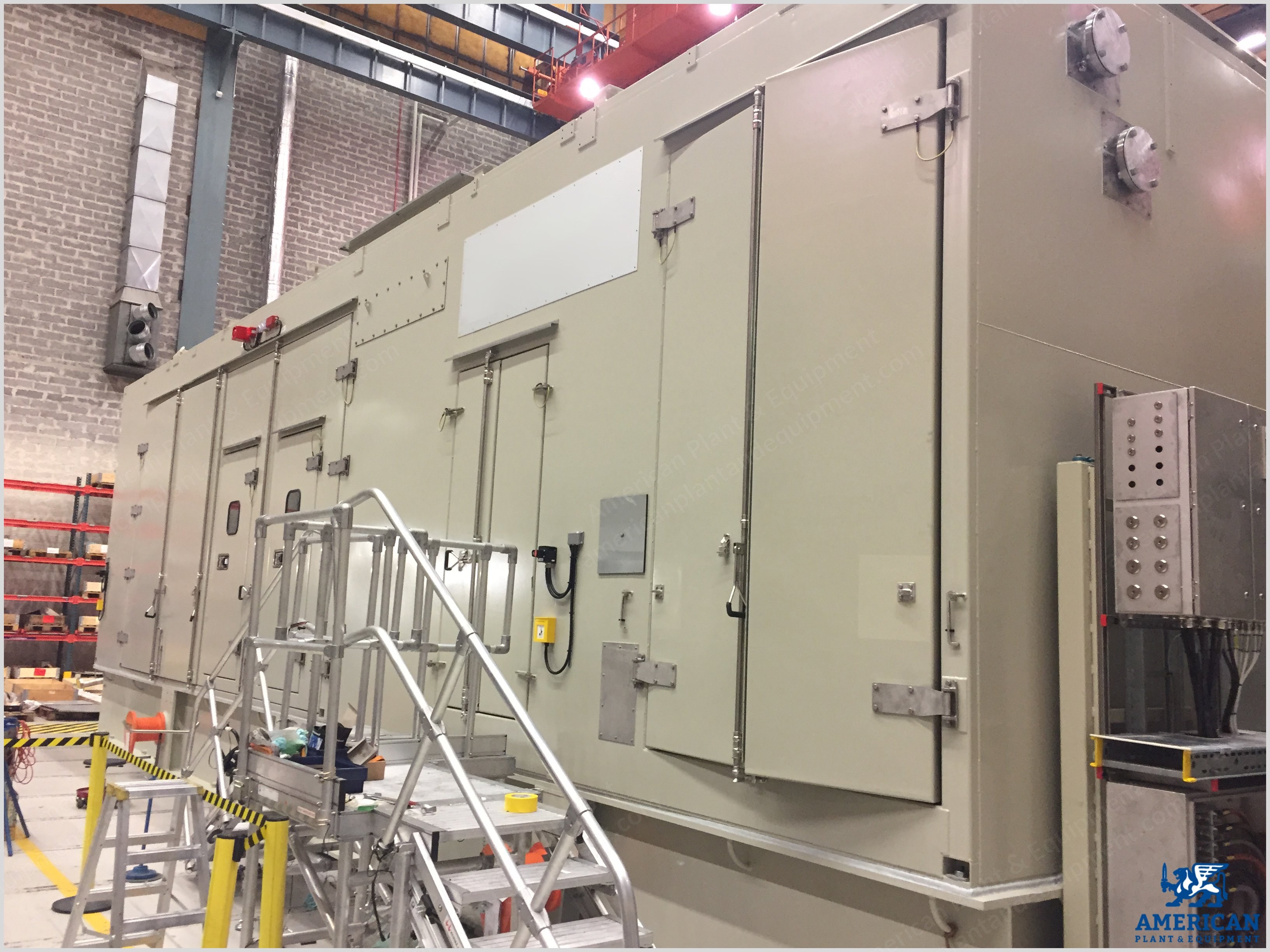
This scope of supply forms a separate unit within the terminal points (utilities/consumables such as auxiliary power, fuel, water, washing detergent, instrument air, lubricating oil and grease are excluded).
Alternative configurations are available.
Siemens model SGT-800 gas turbine power generation for onshore applications comprises the following.
Gas Turbine Equipment
Single shaft designed core engine with a nominal rating of 54 MW.
The engine is arranged for cold end drive and meets electrical ISO conditions.
Compressor inlet casing and inlet bellmouth casing.
Two bleed valves for air bleeding during start up and shutdown.
One annular third generation dry low emission combustion chamber including 30 low emission burners.
Vibration probes of accelerometer type.
Combustion Air Inlet System
Filter house with service platform and ladder.
Two sided pulse clean filter system with two filter stages, class F7 pulse filters as first stage and static class E10 disposable high efficiency filters as second stage.
Support structure for filter house.
Silencer.
Exhaust Gas System
Insulated axial exhaust diffuser with support.
Stack height: 18 m above ground.
Prepared for installation of diverter valve (diverter valve not included).
Exhaust stack including bellows, transition piece and silencer with internal insulation.
Base Frame For Gas Turbine And Gas Turbine Enclosure
Enclosure for weather and noise protection equipped with ventilation, main and emergency lighting and external stairs and walkways.
Left side maintenance opening, looking from exhaust towards inlet.
Internal walkways.
Ventilation For Gas Turbine Enclosure
2 x 100% AC driven fans creating atmospheric underpressure in gas turbine enclosure; the fan unit is placed outside the enclosure.
One-stage disposable barrier type air filter, class G4.
Ducts in carbon steel.
Inlet and outlet are equipped with silencers, weather louvers, and shut off dampers.
Gas Fuel System
Internal gas fuel unit.
Manual shut-off valve and pneumatically operated spring closing gas isolation valve.
Y-type strainer with differential pressure measurement.
Stainless steel piping downstream strainer.
Ventilation valve to atmosphere.
Leakage test of the ventilation and shut-off valves with pressure transmitter at start-up.
Two spring closing, pneumatically operated quick shut-off valves with ventilation valve in between.
AC servo motor operated primary gas control valve to the two primary gas manifolds.
Ignition System
Main gas fuel used as ignition gas.
Pressure regulator, shut-off and vent valves (solenoid operated).
High energy spark plug for cross-ignition.
Starting System
Static frequency converter controlled AC electric start and barring motor with gearbox.
Driver shaft with bearings and free wheel of SSS-type clutch.
Lubricating Oil System
System common for driver and driven equipment.
Carbon steel tank with sub-merged oil heating.
Three AC driven main pumps of centrifugal type, two in operation and one in standby mode; fully automatic and bumpless switch over to standby pump; coast down can be made safely with a single pump in operation.
Electrical motors, fed via frequency converters; DC backup provided on all pumps by a 440V battery to the frequency converters; in case of failure in AC distribution, switch over to DC feeding is made automatically and without interruption.
2 x 100% oil filter with possibility to switch filter during operation.
Oil mist filter with stainless steel casing.
Piping downstream filter in stainless steel.
2 x 100% AC motor driven oil system ventilation fan.
Air cooled lubricating oil coolers of tube type.
Cooling And Sealing Air System
Instruments and components for standard cooling and sealing air system.
Washing And Cleaning System
Turbine compressor washing system.
Water wash trolley.
Electric Generator Equipment
Four-pole synchronous AC generator of salient pole rotor type.
Brushless excitation system with rotating rectifier and PMG for excitation power supply.
Lubrication oil is supplied by the gas turbine package common system.
11 kV, 50 Hz and 1500 rpm.
Power factor 0.8.
Generator cooling IC6 A1 A6, TEAAC.
Line And Neutral Cubicle
Neutral earthing resistor.
Synchronizing Equipment
Automatic and manual (semiautomatic) synchronizing system for two circuit breakers: the generator circuit breaker and one additional breaker; the system is provided with a "synchronizing by-pass" switch for breaker closing against a "dead bus".
Frequency/load control.
Main Gear And Couplings
6600/1800 rpm speed reduction gear of double helical design.
High speed quill shaft between gas turbine and speed reduction gear.
Low speed quill shaft between speed reduction gear and electric generator.
Weather Protection For Electric Generator
Weather roof over the electric generator; material in carbon steel.
Auxiliaries
Anchor bolts for auxiliaries, such as stairs, platforms, coolers, fuel systems etc.
Gas Detection System
Enclosure provided with gas detection system to detect gas fuel leakages.
Fire Detection And Extinguishing System
Fire detection and extinguishing system for the gas turbine room.
1 x 100% CO2 discharge for fire protection.
Central fire suppression unit for alarm and automatic extinguishing.
Manual release buttons located outside each door of the gas turbine room.
Extinguishant release audible and visible alarms.
Extinguishant system distribution pipework, valves and nozzles.
Electrical And Control Equipment
Freestanding LER including indoor lighting, HVAC and external stairs and platforms.
Separate UPS battery module.
Motor Control Center
Motor control center (MCC) including low voltage distribution of IEC 61439 form 4B and withdrawable unit design supplying all consumers, except starting system.
Control System
Micro processor based control, supervision and protection system with PC based operators station; application software in controllers are battery backed-up for two months; license for control system programming included in operator station.
Package protection system is built around a fail safe EC 61508 SIL proven safety controller.
The critical signals work according to the principle of 1oo2.
Main control and monitoring of the gas turbine contains systems and programs to perform both open and closed loop control; main tasks are analogue and binary handling, sequencer for start and stop and gas turbine set supervision and monitoring.
Gas generator speed and temperature control.
PC and Windows 7 based operators interface with necessary software to operate the package in all operation modes; rack type computer with redundant hot-swap, RAID controllers.
Communication, hardwired interface and Modbus serial.
Specifications
Origin: Germany
Fuel type: Gas Fired
Request a Quote
✓
Request sent
Thank you, our team will reply to you shortly.
Direct access to our team
Email American Plant & Equipment
Tell us what you want to buy, source, finance, or sell. A machinery specialist will follow up with you.
✓
Thank you. Your request is with the American Plant and Equipment team.
A machinery specialist will follow up with you.
Machinery updates
Subscribe to our email list
Tell us which industries you follow and we will send you the machines that match.
✓
You are on the list.
We will email you when machines that match your interests come in. Unsubscribe from any message.