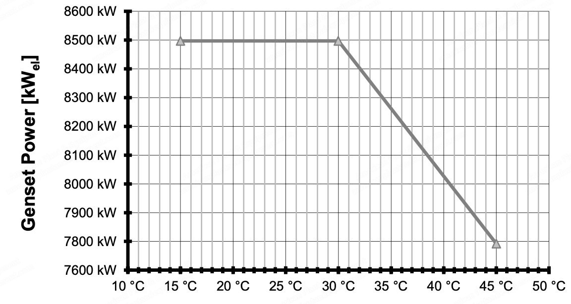
Supply includes 5 x 8500 kWel MAN engine 8L51/60DF
All engines are brand new, never used or installed, currently in original OEM packing under clean and dry storage, ready to dispatch
BOP to be procured; quoted price only for the engine
Purchase orders for all BOP components have to be made; delivery period based on OEM terms and conditions
Engine Details – MAN 18V48/60 TS
Year of manufacturing: 2014
Running hours: approximately 5000
Supply includes 3 x 19305 kWel MAN engine 18V48/60 TS with BOPs and bulk
BOP available (some equipment to be purchased)
Quoted price includes engine plus BOP (excluding tax)
Site Conditions
Altitude above sea level: 5 m
Maximum wet bulb temperature: 30 °C
Minimum ambient air temperature: 15 °C
Maximum ambient air temperature: 45 °C
Operation outside these limits is without guarantee
Generating Set Specifications
Number of generating sets: 5
Engine type: 8L51/60DF
Engine speed: 500 min⁻¹
Lube oil pump: engine driven
HT cooling water pump: engine driven
LT cooling water pump: engine driven
Electrical System
Operation mode: grid parallel
Frequency: 50 Hz
Power factor cos φ (lagging): 0.85
High voltage: 110 kV
Medium voltage: 11 kV
Low voltage: 400 V
Foundation Design
Code: DIN-EN-1998-1
Peak ground acceleration (PGA): 0.2 g (probability of 10% to be exceeded in 50 years, return period of 475 years, based on reference ground with shear wave velocity > 800 m/s)
Soil type: D and E
Importance factor: 1.0
Lube Oil Requirements
Engine lube oil must be in accordance with requirements as stated in section 9.1.1
Viscosity class (40°): SAE40
Cooling System
Cooling method: radiator
Cooling system designed for cooling water in accordance with requirements as stated in section 9.1.2
Engine cooling water circuits without glycol content considered
Fuel System
Fuel gas system designed based on natural gas and pilot fuel oil in accordance with requirements as stated in section 9.1.6
Engines can be operated on diesel fuel oil in accordance with requirements as stated in section 9.1.3
Engines can be operated on heavy fuel oil in accordance with requirements as stated in section 9.1.4
Below 10% engine load, the engine will be operated on diesel oil
Different lube oil qualities (for HFO/gas operation) are required; installation of two independent lube oil storage tanks is recommended
Intake Air and Ventilation
Ambient air: free of dust, salt and sand, aspirated from outside power house
Intake air must be in accordance with requirements as stated in section 9.1.7
Power house ventilation air is blown directly onto the alternator
Maximum temperature inside power house at floor level next to engine/alternator: 55 °C (Tambient + 10 K)
At gallery level, temperature of 60 °C (Tambient + 15 K) is permissible
Alternator design temperature: 48 °C
Frequency and Load Limits
Maximum continuous engine output ensured at mains grid frequency exceeding up to max. +3%
At frequency drop to max. -5%, power output continuously reduced to 95% MCR
Operation permitted up to +5% frequency fluctuations for maximum 120 seconds
Maximum permissible mains grid frequency deviation: ±5%
In grid parallel operation, frequency varies according to current consumer load and input from power suppliers
Power Fluctuations
Power train of generating set acts as a torsional vibration system consisting of engine, coupling and generator
Reciprocating engine, power grid, and other consumers and producers excite the system
Active power at generator terminals is not completely constant; additional power oscillations occur
Power fluctuations do not affect operational safety of the generating set
Behavior is in accordance with ISO 8528-5 and does not affect net stability in an unacceptable range
Gas operated engines tend to show higher load fluctuations than engines operated on diesel fuels
Request a Quote
✓
Request sent
Thank you, our team will reply to you shortly.
Direct access to our team
Email American Plant & Equipment
Tell us what you want to buy, source, finance, or sell. A machinery specialist will follow up with you.
✓
Thank you. Your request is with the American Plant and Equipment team.
A machinery specialist will follow up with you.
Machinery updates
Subscribe to our email list
Tell us which industries you follow and we will send you the machines that match.
✓
You are on the list.
We will email you when machines that match your interests come in. Unsubscribe from any message.