
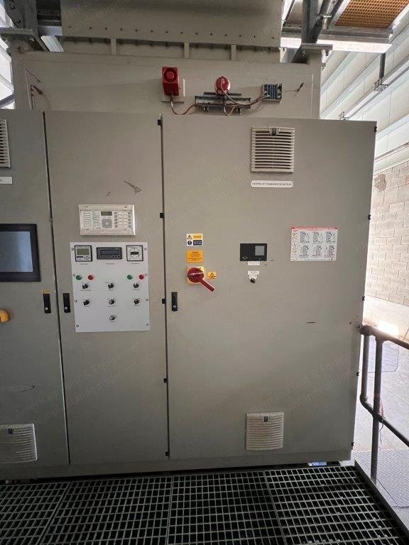
Description
Overview
State-of-the-art power plant system tailored to meet specific requirements and operational needs
Comprehensive overview of the power plant system with detailed specifications, performance characteristics, and associated technical documentation
Model year: 2017
Fuel type: natural gas
Power output: 12.9 MW
Voltage: 11 kV
Frequency: 50 Hz
Scope of Supply
CX400 gas turbine packaging
Centrex SCADA system
Auxiliary transformer
MVSG (medium voltage switchgear)
Low voltage distribution panel
125 VDC – 40 A charger
Gas Turbine Package – General
Total accumulated running time of 5,000 hours, which includes factory test running and commissioning at first installation
Presently deployed in a location where it was already assembled
Model year: 2017
Gas Turbine Generator Package – Driven Unit (Generator)
AC generator with specifications: 11 kV, 3-phase, 50 Hz, 4-pole configuration, power factor of 0.8
Salient-pole design with brushless excitation
Incorporates a permanent magnet generator (PMG) for the automatic voltage regulator (AVR) power supply
Equipped with filter ventilation and class 'F' insulation, ensuring total temperature rise within class 'F' standards
Includes instrumentation for monitoring bearing temperature
Features lubricating oil piping connecting the gas turbine to the driven unit
PMG is situated on the exciter base between the exciter and the non-drive end (NDE) bearing
Neutral earthing resistor (NER) installed on the skid frame
Automatic voltage regulation facilitated by the Basler digital excitation control system (DECS-250N), a microprocessor-based device
Programmed with system parameters and regulation settings offering functions: automatic voltage regulation (AVR), manual or field current regulation (FCR), power factor (PF) adjustment, reactive power (VAR) control
Gas Turbine Package – Gas Turbine Engine
Core engine – twin shaft design
Combustion system – dry low emissions (DLE)
Engine arranged for hot end drive
Engine bearing temperature instrumentation
Gas Turbine Package – Start System
Hydraulic motor and pump – AC electric motor driven
Gas Turbine Package – Gears, Couplings and Guards
Main speed-reducing gearbox – epicyclical type, output shaft speed 1500 rpm
Gearbox seismic vibration instrumentation
Auxiliary gearbox incorporating drives for start system and lubricating oil pump drive
Coupling – high-speed, flexible element dry type – turbine to gearbox drive
Coupling – low speed, flexible element dry type – gearbox to AC generator
Coupling guard – high speed (carbon steel) – turbine to gearbox
Coupling guard – low speed (carbon steel) – gearbox to driven unit
Gas Turbine Package – Lubricating Oil System
Integral mineral oil lubricating system serving the gas turbine, gearbox, and driven unit
Lubricating oil pump main – gas turbine gearbox driven
Lubricating oil pump auxiliary – AC motor driven
Lubricating oil pump emergency – DC motor driven
Lubricating oil system filter – duplex filter arrangement with continuous flow transfer valves
Temperature and smart type pressure and level transmitters – aluminum bodies
Lubricating oil tank immersion heater
Lubricating oil breather oil mist eliminator
Gas Turbine Package – Lubricating Oil System Cooler
Air blast simplex lubricating oil cooler
Cooler fan – single (100% duty)
Suitable for a non-hazardous area
Gas Turbine Package – Gas Fuel System
Pilot fuel flow control system with actuator and integrated pressure transmitters
Main fuel flow control system with actuator and integrated pressure transmitters
Rapid-acting gas shut-off valves (2)
Temperature transmitter – aluminum body
Gas fuel block and vent valve assembly
Off-skid gas fuel unit
Gas Turbine Package – Acoustic Enclosure
Acoustic enclosure – painted carbon steel, fitted over gas turbine, gearbox and auxiliaries
Doors for personnel access and maintenance – 85 dB(A)
Integral lifting beam for maintenance
Internal lighting
Acoustic system transmitters – Siemens standard smart type – aluminum
Acoustic enclosure ventilation system
Ventilation air inlet filter pad type – 304L stainless steel
Ventilation inlet and outlet dampers – 304L stainless steel – air operated
Ventilation fan – single – AC electric motor driven
Ventilation air system – negative pressure
Ventilation air silencer – 304L stainless steel
Ventilation air inlet and outlet ducting – 304L stainless steel
Gas Turbine Package – Gas Detection System
2 I.R. point gas detectors (vent outlet)
Gas Turbine Package – Fire Protection System
3 I.R. multi-spectrum flame detectors
2 heat detectors
Single sounder/beacon (end of package)
1 beacon (inside package)
Status indicator (end of package)
MAC (manual alarm contact)
Gas Turbine Package – Fire Extinguishing
Single shot CO2 fire protection system – in accordance with NFPA12
Cylinders housed in a weatherproof cabinet
Extinguishing system distribution pipe work and nozzles
Gas Turbine Package – Combustion Air Inlet System
Combustion air filter – simple static element
Combustion air filter – weather hood
Combustion air filter – mist eliminator
Combustion air filter – EPA filter stage
Combustion air silencer
Combustion air inlet ducting
Gas Turbine Package – Combustion Exhaust System
Exhaust diffuser – ferritic stainless steel – horizontal orientation
Exhaust silencer – ferritic stainless steel hot section
Thermal insulation and aluminum cladding – personnel protection only
Gas Turbine Package – Package Electrical Systems
Control panel designed to provide environmental protection for the CX400 package control panels and its operators
Fully equipped with lighting, power and environmental controls consisting of: 400 VAC – package motors and heaters supply
Internal and external lighting
Industrial 230 V, 50 Hz outlet
The combined control panel consists of a battery charger, UPS, unit control panel for turbine and generator control and monitoring, and motor control center
Synchronizing facility control with two breakers – automatic and manual with check synchronizer
Batteries sized to ensure a safe rundown of the turbine and driven unit in an emergency
Gas Turbine Package – Drawings and Documentation
Standard set of certified information and approval drawings
Operator manual – hard copy
Piping and instrumentation (P&ID) diagram – soft copy
Electrical wiring diagrams – soft copy
Motor control centre drawings – soft copy
Interconnection cable list – soft copy
Site layout and general arrangement – soft copy
Foundation drawings – soft copy
Centrex SCADA System
Each display screen is structured into four panels: system information at the top, status and control functions on the right, navigation and alarm indicators at the bottom, primary display area dedicated to system

Overview
State-of-the-art power plant system tailored to meet specific requirements and operational needs
Comprehensive overview of the power plant system with detailed specifications, performance characteristics, and associated technical documentation
Model year: 2017
Fuel type: natural gas
Power output: 12.9 MW
Voltage: 11 kV
Frequency: 50 Hz
Scope of Supply
CX400 gas turbine packaging
Centrex SCADA system
Auxiliary transformer
MVSG (medium voltage switchgear)
Low voltage distribution panel
125 VDC – 40 A charger
Gas Turbine Package – General
Total accumulated running time of 5,000 hours, which includes factory test running and commissioning at first installation
Presently deployed in a location where it was already assembled
Model year: 2017
Gas Turbine Generator Package – Driven Unit (Generator)
AC generator with specifications: 11 kV, 3-phase, 50 Hz, 4-pole configuration, power factor of 0.8
Salient-pole design with brushless excitation
Incorporates a permanent magnet generator (PMG) for the automatic voltage regulator (AVR) power supply
Equipped with filter ventilation and class 'F' insulation, ensuring total temperature rise within class 'F' standards
Includes instrumentation for monitoring bearing temperature
Features lubricating oil piping connecting the gas turbine to the driven unit
PMG is situated on the exciter base between the exciter and the non-drive end (NDE) bearing
Neutral earthing resistor (NER) installed on the skid frame
Automatic voltage regulation facilitated by the Basler digital excitation control system (DECS-250N), a microprocessor-based device
Programmed with system parameters and regulation settings offering functions: automatic voltage regulation (AVR), manual or field current regulation (FCR), power factor (PF) adjustment, reactive power (VAR) control
Gas Turbine Package – Gas Turbine Engine
Core engine – twin shaft design
Combustion system – dry low emissions (DLE)
Engine arranged for hot end drive
Engine bearing temperature instrumentation
Gas Turbine Package – Start System
Hydraulic motor and pump – AC electric motor driven
Gas Turbine Package – Gears, Couplings and Guards
Main speed-reducing gearbox – epicyclical type, output shaft speed 1500 rpm
Gearbox seismic vibration instrumentation
Auxiliary gearbox incorporating drives for start system and lubricating oil pump drive
Coupling – high-speed, flexible element dry type – turbine to gearbox drive
Coupling – low speed, flexible element dry type – gearbox to AC generator
Coupling guard – high speed (carbon steel) – turbine to gearbox
Coupling guard – low speed (carbon steel) – gearbox to driven unit
Gas Turbine Package – Lubricating Oil System
Integral mineral oil lubricating system serving the gas turbine, gearbox, and driven unit
Lubricating oil pump main – gas turbine gearbox driven
Lubricating oil pump auxiliary – AC motor driven
Lubricating oil pump emergency – DC motor driven
Lubricating oil system filter – duplex filter arrangement with continuous flow transfer valves
Temperature and smart type pressure and level transmitters – aluminum bodies
Lubricating oil tank immersion heater
Lubricating oil breather oil mist eliminator
Gas Turbine Package – Lubricating Oil System Cooler
Air blast simplex lubricating oil cooler
Cooler fan – single (100% duty)
Suitable for a non-hazardous area
Gas Turbine Package – Gas Fuel System
Pilot fuel flow control system with actuator and integrated pressure transmitters
Main fuel flow control system with actuator and integrated pressure transmitters
Rapid-acting gas shut-off valves (2)
Temperature transmitter – aluminum body
Gas fuel block and vent valve assembly
Off-skid gas fuel unit
Gas Turbine Package – Acoustic Enclosure
Acoustic enclosure – painted carbon steel, fitted over gas turbine, gearbox and auxiliaries
Doors for personnel access and maintenance – 85 dB(A)
Integral lifting beam for maintenance
Internal lighting
Acoustic system transmitters – Siemens standard smart type – aluminum
Acoustic enclosure ventilation system
Ventilation air inlet filter pad type – 304L stainless steel
Ventilation inlet and outlet dampers – 304L stainless steel – air operated
Ventilation fan – single – AC electric motor driven
Ventilation air system – negative pressure
Ventilation air silencer – 304L stainless steel
Ventilation air inlet and outlet ducting – 304L stainless steel
Gas Turbine Package – Gas Detection System
2 I.R. point gas detectors (vent outlet)
Gas Turbine Package – Fire Protection System
3 I.R. multi-spectrum flame detectors
2 heat detectors
Single sounder/beacon (end of package)
1 beacon (inside package)
Status indicator (end of package)
MAC (manual alarm contact)
Gas Turbine Package – Fire Extinguishing
Single shot CO2 fire protection system – in accordance with NFPA12
Cylinders housed in a weatherproof cabinet
Extinguishing system distribution pipe work and nozzles
Gas Turbine Package – Combustion Air Inlet System
Combustion air filter – simple static element
Combustion air filter – weather hood
Combustion air filter – mist eliminator
Combustion air filter – EPA filter stage
Combustion air silencer
Combustion air inlet ducting
Gas Turbine Package – Combustion Exhaust System
Exhaust diffuser – ferritic stainless steel – horizontal orientation
Exhaust silencer – ferritic stainless steel hot section
Thermal insulation and aluminum cladding – personnel protection only
Gas Turbine Package – Package Electrical Systems
Control panel designed to provide environmental protection for the CX400 package control panels and its operators
Fully equipped with lighting, power and environmental controls consisting of: 400 VAC – package motors and heaters supply
Internal and external lighting
Industrial 230 V, 50 Hz outlet
The combined control panel consists of a battery charger, UPS, unit control panel for turbine and generator control and monitoring, and motor control center
Synchronizing facility control with two breakers – automatic and manual with check synchronizer
Batteries sized to ensure a safe rundown of the turbine and driven unit in an emergency
Gas Turbine Package – Drawings and Documentation
Standard set of certified information and approval drawings
Operator manual – hard copy
Piping and instrumentation (P&ID) diagram – soft copy
Electrical wiring diagrams – soft copy
Motor control centre drawings – soft copy
Interconnection cable list – soft copy
Site layout and general arrangement – soft copy
Foundation drawings – soft copy
Centrex SCADA System
Each display screen is structured into four panels: system information at the top, status and control functions on the right, navigation and alarm indicators at the bottom, primary display area dedicated to system