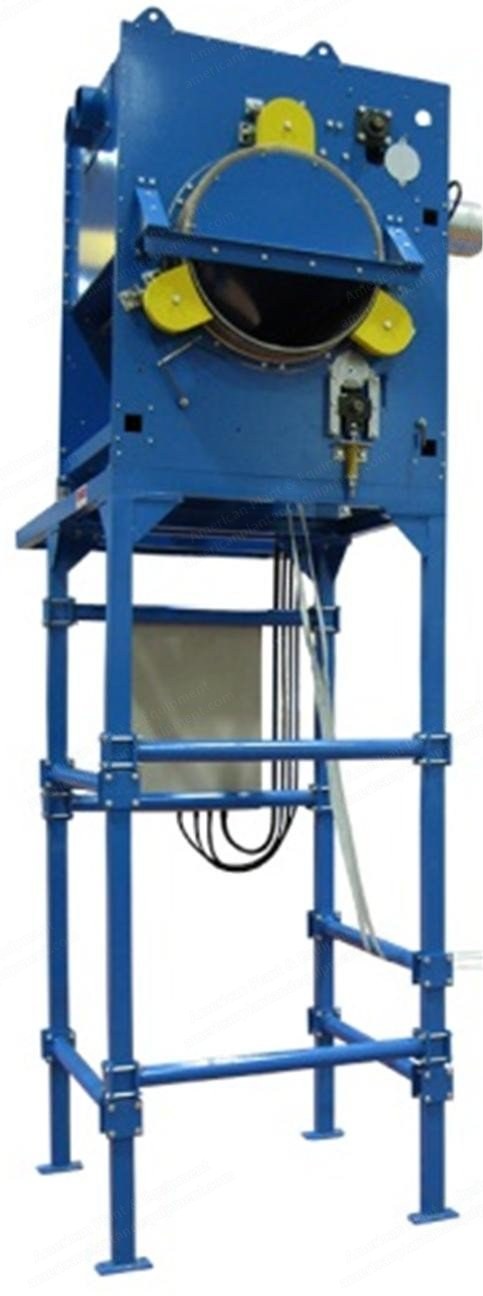
NovaStar, T4.0, 2015, End of Line Winder, 4000mm Working Width, Pneumatic Accumulator
Scroll to zoom
100%
Description
Product Data
Product to be processed: Needlepunched nonwovens
Product width: 4.000 mm
Basic weight: 200 – 600 g/m²
Roll diameter: maximum 1.200 mm
Line Data
Working speed: 1 – 20 m/min
Painting of machines: Light grey RAL 7035
Painting of control and board panel: Light grey RAL 7035
Painting of carters: Light grey RAL 7035
Painting of guards dangerous parts: Orange RAL 2004
Painting of walls and protection doors: Black RAL 2009
Operator side compared to the running sense: To be confirmed
Standards: DIN – ISO – IEC – VDE
Indication units: Metric
Temperature environment: From 5° C to 35° C
Compressed air pressure: 6 BAR
Maximum moisture: 65%
Tension of power: 3 x 460V AC ±5%
Tension of auxiliary: 120 V AC 24V DC
Frequency: 60 Hz ± 5%
Machine Description
Pos. 1.0 – Pneumatic Accumulator T4.0
Main structure in painted steel.
Accumulation capacity 40 Mt.
Material load is min. 0,01 kg/cm, max. load is 0.1 kg/cm.
Electric pneumatic command panel on console table and machine board L.S.
Electronic checking system of tension on accumulator.
The control system of tension on product is handled automatically by the touch panel; a proportional valve is controlled automatically; the tension adjusting on the product is automatic, different pressures can be set in the two phases of accumulation and disaccumulation, you can parameterize the pressures with proportional system from the beginning to the end of accumulation/disaccumulation.
Pos. 2.0 – End of Line Winder T4.0
Base with cylinders.
Structure in painted steel structural work.
2 support cylinders Ø 420 covered with PVC adhesive tape.
1 inverter-driven servo-ventilated motor for the 2 cylinders.
2 levers mounted on lateral shoulders and automatic pneumatic roll expulsion system.
Footway as indicated on the layout.
Presser cylinder
No. 1 pressing cylinder with 2 servo-ventilated motors driven by frequency converter.
Sliding system on prismatic guides with recirculation spheres runners and tempered wheels.
Synchronism shaft with racks.
Lifting with pneumatic cylinders equipped of safety valves and quick discharge tools.
No. 1 pneumatic material locking system.
No. 1 pneumatic command panel of presser cylinder.
Banana roller
1 banana roller rubber covered, driven, installed before the slitting cutting unit.
Presser roller under winding cylinder
No. 1 pressing cylinder rubber covered placed under the winding cylinder.
No. 1 pneumatic command panel of presser cylinder.
Predisposition of frame for future installation of a further deviation roller.
Spindle shaft
All the sliding components are on tempered wheels with ground tempered guides.
Manual transversal shifting of spindles, pneumatic locking system with on-board valve.
Automatic pneumatic lifting and lowering of spindles.
Spindles position register, all low, and realized with manual mechanical strike to adjust according to the carton core type.
Pneumatic independent opening/closing of spindles, stroke 150 mm.
Min. spindles dimension, all closed, 2.500 mm.
Spindle couples included: no. 1 inner Ø 49 mm, no. 1 inner Ø 75 mm.
Crosscut on machine delivery
1 motorized blade Ø 150, cross moving through motorized linear axis.
All the guides and the shifting wheels are tempered and ground.
Transversal cutting speed is 1 m/sec.
Slitting unit
No.4 driven knives at pressure cut Ø 105 mm.
No. 1 tempered cylinder.
No. 1 drive with frequency converter.
The cross moving is manual.
Threading system of fabric for change of roll
1 automatic pneumatic threading system of the material upon change of roll operation.
The unit is positioned in the unloading roll area and by means of a blow of air it enables the automatic winding of the material on the carton core.
System suitable for basic weights up to 600 g/m².
Such system does not ensure the automatic change of roll unless the carton core will be provided of an adhesive tape.
Fabric delay rollers
No. 4 Idle cylinders in painted steel, delay fabric in machine inlet, favored the passage in the slitting group.
Creel cylinder
Counter meter
No. 1 meter counting wheel in contact with the fabric.
Spreader cylinder
No. 1 spreader cylinder rubber covered Ø 150 mm necessary to remove folds in winding phase.
Manual adjusting angle of incidence.
Drive with frequency converter.
Transmission with double belt.
Pos. 3.0 – Electric Plant
The standard features of the electrical supply are the followings:
Electrical main supply 3PH+PE 460Vac 60Hz (if there are not other specifications). It’s strictly recommended to protect the electrical main supply with ground fault circuit breaker type “B”.
Auxiliary circuits voltage 120Vac - 24Vdc.
Electrical cabinet protection IP55 (CEI EN 60529) color RAL7035 (if there are not other specifications).
Main electrical switch lockable if opened.
Signal lamp if electrical cabinet doors are opened with voltage on.
Electrical cabinet internal light.
Electrical cabinet air cooling ventilation.
Electrical cabinet air cooling system (optional).
Safety devices type PL”e” following EN ISO 13849-1, safety class 4 following EN 954-1, SIL CL 3 following EN IEC 62061 (double channel safety with short circuit detection).
Emergency pushbuttons circuit interface available for production line.
Machine access protections with electrolocked devices (included).
Local safety devices (safety rope, safety mat, photoelectric barrier …) installed on area where are not available fixed machine access protections (included).
Motor drives Siemens Sinamics:
Integrated safety functions following IEC 61800-5-2.
EMC class C2 following EN 61800-3.
Servo-ventilation for continous service motors.
Closed-loop control for main process motors (if required).
Over-temperature motor control (PTC sensor) if working temperature >40°C.