For plastic films, polyethylene, tarred paper, and various types of nonwoven.
Can process pet virgin/recycled and bicomponent webs.
Hourly production: 1000 to 2000 kg/h.
Working speed: maximum 100 m/min.
Total power: 32 kW.
Air pressure: 6 bar.
Maximum material width: 2000 mm.
Weight: minimum 100, maximum 6000 g/m².
Product density: minimum 20, maximum 200 kg/m³.
Maximum thickness: 250 mm.
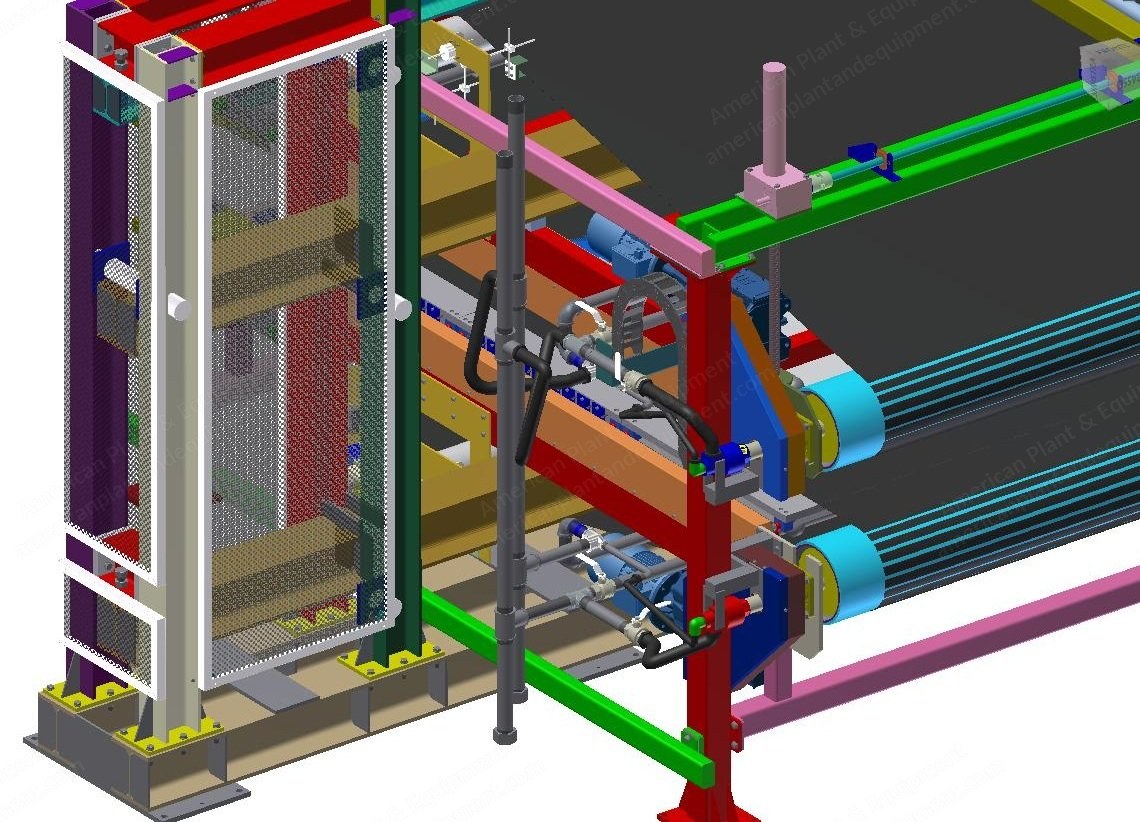
The machine has two main functions: calibration of panel and smoothing of surface.
Normally, the panel enters the machine with two special conveyor belts (one upper and one lower) that are resistant to high temperatures and is slightly squashed to achieve the final desired thickness.
In the first two sections heated with thermal oil, there is a superficial thermo-melting of the panel that creates a smooth surface, while in the second section the surface is cooled and stabilized with exchanger with cold water.
Smoothing is possible on both sides or only on the bottom/top side.
The management of the calibration thickness is automatically set by the operator panel.
Support Frame
Main frame in folded sheet and painted steel profiles, coat panelling in fire painted steel.
The machine is built with cantilever frame to avoid junction on site if the belt breaks.
The junction is made closed at ring to allow easy removal and replacement of the belt.
Calibration
Calibration is ensured by two pairs of jacks; this solution allows to calibrate the product and get a max. density of 200 kg/m³, the thickness is set by the operator panel and comes from 1 linear transducer mechanically connected to the jacks of ascent and descent of the upper bench.
Useful passage of internal tunnel min. 5 mm, max. 250 mm.
Belt Heating System
The heating area of upper and lower belts takes place in the initial area for a total length of 2 m.
The belts heating takes place with plates thermo-regulated and heated with thermal oil in contact with the belt.
Belt Cooling System
The cooling area of upper and lower belts occurs in the final area for a total length of 1 m.
The belt cooling takes place with plates, capacity of 10,000 kg-frig each.
Temperature of the liquid refrigerant 8° to 15° C.
Electrical Plant
Power supply 3ph+pe 400 vac 50 hz (unless otherwise specified).
Carpentry cabinet ral7035.
General switch of electric board with the door lock function (operation lockable).
Voltage indicator with open doors of electric board.
Illumination electric board.
Ventilation system electric board.
Air conditioning inside electric board (optional).
Safety devices class pl and in accordance with en iso 13849-1, category 4 according to en 954-1, sil cl 3 according to en iec 62061 (dual channel operation with detection of shorts).
Drives with integrated safety functions according to iec 61800-5-2, respectively safe torque off (sto), safe stop 1 (ss1), safety limited speed (sls).
Drives with emc according to en 61800-3.
Servoventilation continuous service.
Adjusting closed loop main utilities process (motor with encoder).
Overheating engines control through ptc probe if ambient temperature > 35 °C.
Plc control system.
Integration of decentralized periphery profibus dp.
Setting up remote assistance - communication with third-party tcp/ip industrial ethernet.
Setting up analog input reference speed line.
Setting up analog output reference speed line.
Services - hmi (touch panel).
Column acoustic-light signal.
The power supply includes the delivery of the following documents at the end of work: schematic (english unless otherwise specified), operator's manual (english unless otherwise specified), list of recommended spare parts.
Pneumatic Plant
All components are installed on the board machine (including the reducer group and air treatment) while feeding tubes are deposited in the channel of the board machine.
Request a Quote
✓
Request sent
Thank you, our team will reply to you shortly.
Direct access to our team
Email American Plant & Equipment
Tell us what you want to buy, source, finance, or sell. A machinery specialist will follow up with you.
✓
Thank you. Your request is with the American Plant and Equipment team.
A machinery specialist will follow up with you.
Machinery updates
Subscribe to our email list
Tell us which industries you follow and we will send you the machines that match.
✓
You are on the list.
We will email you when machines that match your interests come in. Unsubscribe from any message.