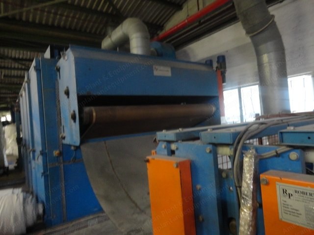
Santex, Thermobonding Line, 2003, 2500mm Working Width, 10-100mm Thickness
Scroll to zoom
100%
Description
Overview
Thermobonding line for the production of bulky nonwovens.
Working width: 2500 mm.
Construction year: 2003.
Second hand (1985) thermobonding oven “Santex”, completely overhauled, provided with mechanic and electric guarantees as new machine.
Suitable to process material with a thickness from 10 mm to 100 mm.
Electric heating.
Use and maintenance manual included.
Contract no. 20446/03 and 20447/03.
Composition
Thermobonding oven, second hand, completely overhauled, provided with mechanic and electric guarantees as new machine suitable to process material with a thickness from 10 mm to 100 mm.
Working width: 2500 mm.
Electric heating.
Supporting and connection system for strato vertical lapper.
Working width: 2500 mm.
Vertical lapper strato: working width 2500 mm.
Longitudinal and transversal cutting machine: working width 2500 mm, 6 longitudinal hand-moving blades, 1 transversal cut.
Winding device: working width 2500 mm, cylinder diameter 350 mm.
General Technical Features
Working width: 2500 mm.
Roll face width: working width + 50 mm.
Material fibres: nonwoven web of polyester or different fibers mixed with 10-25% polyester bi-component binder fibers or different binder fibers.
Machine speed: 1 - 20 m/min (others upon request).
Composition oven: 2 heating zones of 2 m each + 1 cooling section (included in the second zone).
Material transport: transport belts of teflonized glass fibre, open or close mesh fabric below and above the material (others upon request).
Max. distance between belts: 6÷100 mm in heating zones, individually adjustable in each zone.
Power supply: 3 x 380 v + n + e / 50 hz (others upon request).
Machine weight: 18.000 kp.
List of Motors and Relative Power
In-let feeding conveyor belt: m1 power 1.5 kw (driven by inverter).
Vertical lapper strato: m2 power 0.75 kw (driven by inverter) feeding discs; m3 power 0.75 kw (driven by inverter) forming discs; m12 power 0.18 kw strato thickness.
Thermobonding oven: m4 power 2.2 kw (driven by inverter) lower belt towing; m5 power 2.2 kw (driven by inverter) upper belt towing; m6 power 0.12 kw (driven by inverter) web guiding system of lower belt; m7 power 0.12 kw (driven by inverter) web guiding system of upper belt; m8 power 30 kw chamber 1 air circulation; m9 power 30 kw chamber 2 air circulation; m10 power 3 kw exhaust; m11 power 2.2 kw material cooling fan; m13 power 0.75 kw chamber 1 thickness; m14 power 0.37 kw chamber 2 thickness; power 30 kw fix heaters; power 30 kw fix heaters; power 120 kw modulating heaters; power 120 kw modulating heaters.
Longitudinal and transversal cutting machine: m1 power 0.75 kw (driven by inverter) in-let; m3 power 1.8 kw (driven by inverter) longitudinal blades; m4 power 0.75 kw transversal blade; m5 power 1.5 kw transversal blade; m6 power 0.12 kw calander 1 thickness; m7 power 0.18 kw lifting and lowering longitudinal blades; m8 power 0.12 kw calander 2 thickness.
Winding device: m2 power 1.5 kw (driven by inverter).
Environmental Conditions for Running
The working environment must be conditioned at an average temperature of 20-25° C and humidity of 50 %.
The second hand (1985) thermobonding oven "Santex" is provided with 3 outlets: one for air circulation smoke exhaust (see drawing no. “layout 20440”, pos. 01); one for smoke exhaust coming directly from burners (see drawing no. “layout 20440”, pos. 02); one for exhaust air coming directly from the cooling material fan (see drawing no. “layout 20440”, pos. 03); this air is usually ejected outside in summertime and inside in wintertime (since air comes from working room and therefore clean enough).
Transport and Installation
All the machines of the line are supplied disassembled.
For moving all these parts it is necessary to use a crane and/or fork truck.
The parts that need particular attention (like control board, etc.) are supplied well-packed in boxes or wooden crates.
No machine needs foundations; the only condition is a sufficiently smooth floor with a load capacity of about 300 kp/m².
The oven consists of a main structure and has been studied so that its assembling is easy (refer to drawing no. “20440 11”).
The oven is supplied disassembled in the following pieces: entry part (pos. 1); exit part (pos. 2); heating chamber 1 and heating chamber 2 (pos. 3 and 7”); piping: have to be assembled as last parts (pos. 7); blowers lifting system of chamber 1 and chamber 2 (pos. 5); air circulating motor for chamber 1 and chamber 2 and relative sliding plates, cooling motor, smoke exhaust fan (pos. 9 and 11); upper and lower belts are to be assembled (during transport they are placed inside a carton box).
Assembling: after having marked on the ground where the oven has to be placed (with extreme borders and relative middle line) go on with oven assembling as follows: position the 2 heating chambers joining one with the other by means of the proper screws (see drawing no. “20440 1103”); before join them together put the high temperature gasket and, if it is possible, a sufficient quantity of high temperature silicon on the joint perimeter to avoid future dispersion of smokes; true and level machine perfectly; mount the entry part, fixing it by means of the proper screws (see drawing no. “20440 1101”); join the feeding conveyor belt (pos. 12) with the chamber 1 (pos. 1) of the oven by means on the proper supports.
Request a Quote
✓
Request sent
Thank you, our team will reply to you shortly.
Direct access to our team
Email American Plant & Equipment
Tell us what you want to buy, source, finance, or sell. A machinery specialist will follow up with you.
✓
Thank you. Your request is with the American Plant and Equipment team.
A machinery specialist will follow up with you.
Machinery updates
Subscribe to our email list
Tell us which industries you follow and we will send you the machines that match.
✓
You are on the list.
We will email you when machines that match your interests come in. Unsubscribe from any message.