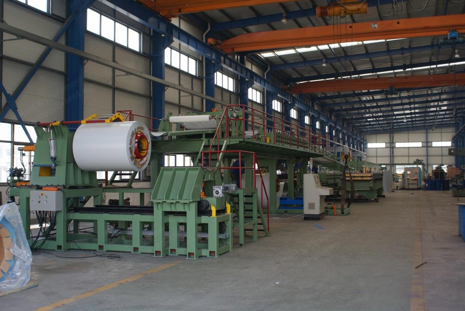
Dimensions: approx. 140 meters x 18 meters x 6.5 meters
Total power: 400 kW
Can make 3 kinds of panels: roof, wall panel I, and wall panel II
Roof Panel
Thickness: 20 mm to 150 mm
Width of upper steel sheet: 1250 mm
Width of bottom steel sheet: 1070 mm (machine has a side cutter to cut from 1250 mm sheet)
Thickness of steel sheet: 0.4 to 0.8 mm
Wall Panel I
Thickness: 40 mm to 150 mm
Width of upper and bottom steel sheet: 1220 mm
Thickness of steel sheet: 0.4 to 0.8 mm
Outside surface has wave profile
B = 50 to 200 mm
Wall Panel II
Thickness: 40 to 150 mm
Width of upper steel sheet: 1220 mm
Width of bottom steel sheet: 1070 mm
Thickness of steel sheet: 0.4 to 0.8 mm
Outside surface has wave profile
B = 50 to 200 mm
Included Components
Two sets of uncoiler with coil car
Feeding table, pinching rollers, steel sheet transverse cutting device, steel sheet surface protective film covering device, steel sheet ribbing group
Roll forming machine (4 sets) and platform (up and down)
Conveyer rack
Pre-heating room
Foaming and the maturing caterpillar/double belt machine (24 m length), 6 sets side nylon seal blocks to make different thickness wall panel and roof panel, one set of blocks for supporting roof panel
Heating and heat insulation system
Panel automatically cutting system
Optional: cooling system
Optional: conveyer, automatic stacking machine
Optional: packing machine
Optional: electric control and communication link control system
Main Machines and Technical Data
Two sets of decoiler
Automatic and hydraulic, can be used to uncoil steel coil which is maximal 1300 mm wide, no more than 15 ton weight, and steel coiler's inner diameter is about 500 or 600 mm
De-coiler and coiler car for bottom steel sheet
The hydraulic de-coiler is used to hold and drive the steel coil that is being fed into the roll forming machine
The de-coiler allows for a quick change of steel coil with minimal manual labor
The de-coiler is powered with a feedback system that ensures the roll former is not required to turn the coil
The de-coiler will turn as required to reduce the potential for over coiling
Maximum coil mass: 15,000 kg
Nominal coil ID: 500 mm supplied with additional spaces to use 600 mm above
Maximum coil OD: 1300 mm
Maximum coil width: 1300 mm
Machine consists of the following major items:
Machine frame
Overhung shaft with roller bearing
Drive motor and chain
Hydraulic power pack (shared power pack on top/bottom coil)
Hydraulic cylinder of expansion/retraction
Solenoid valves
Electrical control system
Limit system to allow positioning of de-coiler for different feed positions, manual positioning with position indicator
Coiler car-powered loading bed to aid in loading to the de-coiler
Main support structure for main profiling of the steel sheets
The main support structure: a top and bottom section for the top and bottom profiling of the steel sheets, include face profiling and the edge profiling
The main sections of this structure include:
Main support floor for top and bottom profiling stations
Moveable bottom section to allow production of different panels
Access stairs to support platform
Handrails and floor kick plate to raised platforms for safety
Face profiling roller stations
Face profilers are located in the front of the roll forming station to allow all face profiles to be made as required in the specifications
Coil slitter for top steel sheet
To allow over width steel to be used on the product line, a dual wheel type slitter is supplied to allow up to 100 mm of excess steel to be slit from the coil during production
At the end of the production, the operator can remove the slit coil roll and dispose of as required
Protective film application for top steel sheet
A support shaft and holder is provided to allow plastic protective film to be applied to the outside skin of the coil
The protective film coil is located just prior to the feed in pinch rolls for feeding of the coil, ensuring position pressure in applying of the film
The loading of the film is manual by the operator prior to the start of production
Coil slitter and application for bottom steel sheet
See the specification for item 5.2.3
Protective film application for bottom steel sheet
See the specification for item 5.2.3
Top and bottom steel processing stations
The steel processing station consists of main steel fabrication housing the following entities:
Sheet cutoff
Two sheet cutoffs allow for the cutting of partially used coils during the production run when the entire coil feed is not required
The cut is made when the shaft wheel is driven across the coil by a transmission chain and cuts against the top rail
The sheet cutoff does not have to stop production during cutting
Sheet guides
As the skin is de-coiled and fed into the roll forming station, a series of adjustable sheet guides ensure that the coil is held and presented in the correct position for forming and prior to laminating
These sheet guides are designed to be variable in width and are adaptable to the various panel types
Roll forming machine
Edge joint roll former stations (for cassette mounting of tooling)
The station consists of both upper and lower forming group being top male side, top female side, bottom male side, bottom female side
Each group is adjustable by electric screw thread and indicator to allow for width adjustment for each panel type and width
The former groups are driven both top and bottom shafts through gearing
The shafts remain fixed in the machine and rollers are interchangeable as required
Each roller group is driven with a speed referenced of the bottom main-sail press drive motor encoder to ensure speed is matched
The clearance adjustment between top and bottom former pairs is by manual screw adjustment
The interlocking
Request a Quote
✓
Request sent
Thank you, our team will reply to you shortly.
Direct access to our team
Email American Plant & Equipment
Tell us what you want to buy, source, finance, or sell. A machinery specialist will follow up with you.
✓
Thank you. Your request is with the American Plant and Equipment team.
A machinery specialist will follow up with you.
Machinery updates
Subscribe to our email list
Tell us which industries you follow and we will send you the machines that match.
✓
You are on the list.
We will email you when machines that match your interests come in. Unsubscribe from any message.