Operating speed: 5 – 30 m/min depending on the coating and application
Drive side: left
Voltage: 415 V, 50 Hz or as per customer
Air: 6 bar pressure, oil and water free
Heating: by gas burners (gas to be supplied at specified pressure and volume)
Unwinding From “A” Frame
Capacity 1500 mm diameter: with positive unwinding with geared motor
Pulling nip between “A” frame with load cell to control the unwinding tension
Coating Head (2)
Max web width: 2200 mm
Coating width max: 2100 mm
Coating weight dry: 8 to 300 gsm
Solid contains %: 45 to 60%
Roller face width: 2000 mm
Mechanical speed: 2.5 to 15 m/min max
Main coating roller: hard chrome plated D345
Required power load: 7.5 hp approx
Input voltage: 3 phase 415 V / 50 Hz or as per customer
Air volume: 10 to 20 cfm @ 7 kg/sq cm pressure
Coating method: knife on roll – dry weight min 40 and max 300+ gsm, depends on solid contains and viscosity
Coating method: knife on air – dry weight min 8 and max 20 gsm, depends on solid contains and viscosity
Knife Coater
Frame structure made out of 27 mm thick machined plates
Dia. 345 mm chrome plated coating roller having a concentricity within 10 - 15 microns mounted on bearings with arrangement of minimum clearance
210 mm dia. chrome plated draw roller with pneumatically operated rubber nip roller dia -170 mm for positive pulling from unwind stand
Knife coating unit with inbuilt arrangement of knife on roll, knife on air and dual knife rotation system
The knives (knife on roll and knife on air) made out of carbon steel – C45, all surfaces ground and hard chrome plated
A.C motor gear box to rotate the knife holder and bring in position either on knife at desired angle
A micro adjustment system to adjust the gap of knife individually / simultaneously by motorized operating system, min gap 50 microns (0.050 mm) can be set over roll
Digital indication of gap between knife and roller at both side LH and RH
Pneumatically operated locking device for knife rotation and knife slide for air
Pneumatically operated quick lifting cylinder arrangement to lift the knife upwards allowing to pass the joint while running
Side limiters motorizes on the knife holder itself, facilitating the web width adjustment for both knives (knife on roll and air)
Motorized operated paste delivery device on top side for uniform paste supply on fabric width, with AOD pump, fitting and liquid level controller assy
A necessary pneumatic elements such as pressure switch, regulators, FRL unit, toggle valves and solenoid valves from standard manufacture
A rubber coated bow roll – D90mm x 2000 at entry of coating roller
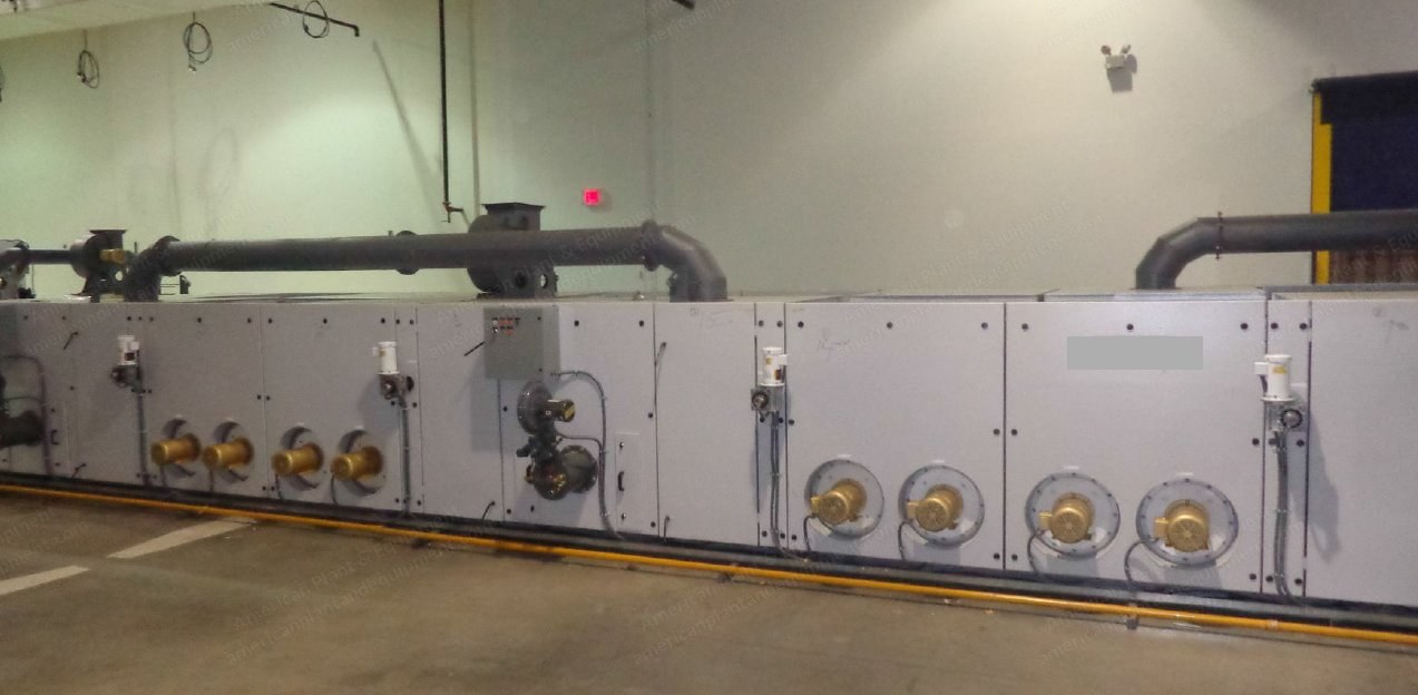
5 Chamber Stenter, Pin & Clip Type
Operators platform
MS fabricated box type body (painted) with powder-coated doors
One cross beam with machined and polished plated to rest the rail and enable its free movement based on the signals received from in feed device
Two guide rollers
Two operator control cabinets housing push buttons, speed indicators, ampere meters and other controlling buttons
Fabric transportation: one set casted rails with ground finish enabling smooth sliding of the chain, 3.3 m entrance track with ball bearings set
One set spring operated chain tensioning system
One set chain with pin & clip type
One set limit switches to control chain tensioning
One pair E+L KR 43 photocell with FR 15 sensors for fabric edge sensing and controlling the position of the inlet rails
Dryer (Varioflow) – 5 Chambers
Frame structure constructed with heavy angle section
Chamber length: 3 m each
Interiors will be high temperature resistant painted
Closed circuit air circulation
Individual blowers for top and bottom jets - 4 nos
Directly couple blower motors per chamber. Air ratio between top and bottom jets can be controlled and adjusted easily at fingertip through touch screen at the central control unit
Special feature for coating – if desired only top or bottom air can be used individually which will reduce the connected load to 50%. This is not possible in systems with single blower for top and bottom jets where mechanical dampers are used to control the air flow
Gas fired - Maxon make burners, model Valupak 300, one per chamber (total 5 nos.)
Dual filters - easily removable from outside for cleaning even when the machine is running
Insulation is rockwool with 96 kg/m3 density – 125 mm thick panels
Door and panel sealing by silicon
Stenter Exit
One set heavy duty bevel gear box rested on machined rails. Driven by AC motor
Bevel gear box driven by spline shaft and AC motor
One no driven MS roller with fillet for fabric take off
One pair de pinning device
Two Nos. Cooling Cylinders
M.S. frame connected with each other with channel tie bar
2 nos. of cooling drum made of stainless steel roll having 400 mm dia will be provided. The drum will be mounted on bearing pillow block with necessary rotary union
One drive with reduction gear box and AC motor
Fabric Winder on “A” Frame
Capacity 1500 mm diameter
One no. load cell for tension control during winding. This load cell is common for both winders as only one winder will operate at a given time
Winders will be with M.S. frame with geared motor (each 3.7 kW) with adaptors
These adaptors will couple on the “A” frame for winding. The drive control system for this winders will be torque controlled VFDs, with PLC and load cell feedback
Electric Control Panel
MS fabricated closed panel with optimum cooling
A/C drives: ABB/Yasikawa make
Switch gears will be Siemens / L&T make
PLC and touch screen controls for controlling and monitoring the process parameters
Interconnecting cables/trays between machine control panel and individual motors and sensors
Request a Quote
✓
Request sent
Thank you, our team will reply to you shortly.
Direct access to our team
Email American Plant & Equipment
Tell us what you want to buy, source, finance, or sell. A machinery specialist will follow up with you.
✓
Thank you. Your request is with the American Plant and Equipment team.
A machinery specialist will follow up with you.
Machinery updates
Subscribe to our email list
Tell us which industries you follow and we will send you the machines that match.
✓
You are on the list.
We will email you when machines that match your interests come in. Unsubscribe from any message.