Torque balls turn the sliding parts with the clutch and limit the travel of the sliding disc and cam sleeve.
The locking balls are carried forward by the cam sleeve and drop into locking holes where they are held by the cam sleeve.
The v-belt ball-lok clutch is available in three basic series.
Belts: A and B.
Keyways: standard for the shaft size on most clutches; when not standard, a key is provided.
Set screws: refer to illustration for set screw locations; pump applications may require an additional set screw due to length of pump shaft; specify length of shaft.
Finish: all exposed and internal parts are finished in a rust resisting finish.
Horsepower capacity: refer to table on opposite page.
Clutch adjustment: there is nothing to adjust, no friction plates to wear out; the belt itself is the only friction element on the v-belt ball-lok clutch.
Shock loading: the variable speed effect of the v-belt ball-lok clutch eliminates belt grab and shock to equipment.
Low speed drives: below 800 rpm, see sprocket clutches.
Disengagement: instantaneous.
Shifting forks or levers: refer to page covering each series.
Lubrication: pressure grease fittings are supplied to lubricate the locking mechanism and sliding disc; light oil is required on hub and center discs of 2, 3, and 4 belt models; in the absence of a pressure grease gun, light oil may be applied to the sliding disc and cam sleeve.
Remote control: the ball-lok clutch is a manual clutch; the extremely light pressures required to engage a clutch, 10 to 35 pounds, allows remote control by means of cable, solenoid or air cylinder; refer to page with illustrations of various remote control installations; the “x” and “xo” series are commonly used in remote control applications.
Ball bearing idlers: are available on most sizes; a ball bearing idler should be chosen when the clutch is required to idle more than 5 to 10% of the operating time.
Marine finish: sealed bearings, etc.
Xo Series Clutches
The finest clutch in the line; specifically designed for marine or outdoor use.
Construction includes double sealed ball bearings throughout, internal stainless steel balls, ball bearing shifting collar and a special lubrication at no extra cost.
Ball Lock Service Tips
Lubrication: lubrication is required for the sliding hub assembly parts only; use a high-temperature, water-resistant grease for best results; grease while in the disengaged position, then cycle to the clutch, engages and disengaged several times; this action will allow the grease to work up into the hub assembly; repeat several times to ensure full coverage; periodically monitor to ensure it is operating with sufficient coverage.
Belts: the standard ball lock pulley models are designed for use with either an “a” or “b” belt; multiple pulley models will not work properly with bonded belts because they cannot disengage the pulley halves; for non-standard belt widths, please consult manufacturer.
Sprockets: the standard models are available for #40 and #50 chain; for non-standard pitch or number of teeth, please consult manufacturer.
Bores: the standard models are available with bores from 1/2” to 1 7/16”; for metric bores and special keyways, please consult manufacturer.
Ball Sprocket Installation Specs
Do not drive the clutch on the shaft; it has been constructed to fit easily on a clean shaft and a good key.
The set screw is exposed by disengaging and rotating the sprocket assembly outward.
Tighten the set screw firmly, and lightly stake the top thread to prevent loosening of the set screw; an alternate method would be to use a liquid locking compound.
The clutch is equipped with a special threaded collar for adjustments; make sure that the chamfered edge of the threaded collar is towards the inside of the clutch so that the chain will not rub on the collar.
With the clutch in the engaged position, tighten the adjustment collar until the sprocket assembly will no longer slip against the lining; tighten the threaded collar firmly in place.
If, after adjustment, the clutch is not sufficiently tight, repeat this procedure until the clutch will not slip.
How To Install Clutch
Do not assemble clutch – it is not easy to assemble, and unnecessary for installation.
Do not drive clutch on to shaft; it has been carefully constructed to fit a clean shaft and good key.
Clutches designed for stub shaft series x must not be mounted too far on shaft or sliding parts cannot completely close.
Set screw is exposed on 1-belt clutch by disengaging and rotating to expose access hole; tighten firmly, and lightly stake top thread to prevent loosening, which would interfere with sliding action.
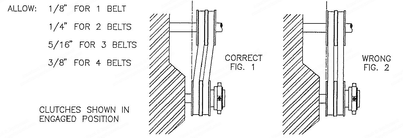
Adjust belt to normal tension with clutch engages (pulley sides closed); if belt is too tight it may not close, or will require excessive pressure to engage; clutch will not close on a dead belt; clutch must be turning; belts should be “in line” when idling with opposite pulley, and slightly “out of line” when engaged; this reduces the tendency of the belt to creep when disengaged.
How To Install Lever Or Shifter Fork
Important – locate and drill a hole in the lever or fork so that it pivots at the center of travel or swing, and moves over-center when engaged or disengaged; this over-hanging weight restrains any tendency of clutch to jar open under extreme vibration.
Request a Quote
✓
Request sent
Thank you, our team will reply to you shortly.
Direct access to our team
Email American Plant & Equipment
Tell us what you want to buy, source, finance, or sell. A machinery specialist will follow up with you.
✓
Thank you. Your request is with the American Plant and Equipment team.
A machinery specialist will follow up with you.
Machinery updates
Subscribe to our email list
Tell us which industries you follow and we will send you the machines that match.
✓
You are on the list.
We will email you when machines that match your interests come in. Unsubscribe from any message.