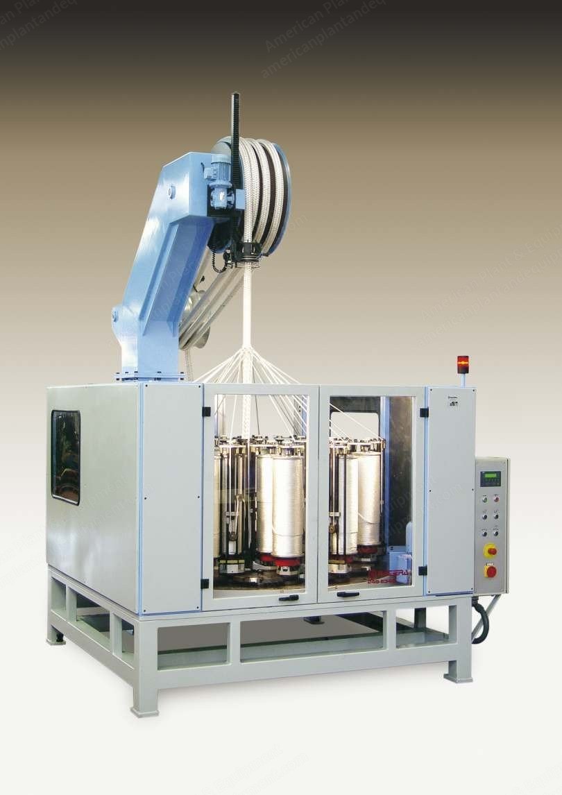
Lower housing made of rolled and weldable steel with oil bath equipped with shaved helicoidal gears transmission
Track plate of perlitic melting, hardness 210 Brinell
Horngears, feet, crossings, and guides of hardened and precision finished, hardness 610 Brinell
Screwed horngears with interchangeable plastic inserts to provide quiet and continuous operation for years
Square underframe made of robust and stable steel construction with square legs of 100 mm
Square overall metallic guard around the housing made of square tube of 60 mm x 40 mm x 3 mm, outside metal sheet cover of 1.5 mm and an inside covering noise one made of isolated material
Methacrilated double front door and a single back one, both sides with a methacrilated window, equipped with safety micro-switches integrated in the hinges (conformity to EC – I.S.O. 11,111)
Drive and Motor
Drive: main motor including all necessary control devices and to prevent motor overload including an encoder to control braider main motor
Power of 2 HP – 1.5 kW to 1500 RPM
Horngear speed: 60 RPM
Voltage: 220 V – 50 cycles – 3 phase
Installation and electrical box for voltage 208 to 240 volts prepared for one frequency shifter of 3 HP = 2.2 kW to adjust braider for main-motor speed including all electrical components for its adjustments, and a second one of 1 HP = 0.75 kW to adjust speed of braider take off system
Control and PLC
PLC with a screen to control and inform
Helix pitch
Open door detector
Stop for the anti-tangling switch
Number of horngears’ RPM
Forward and reverse rotation
Counter indicating the number of meters
Counter indicating the total number of meters
Time counter
Front Panel
One press on button
One press off button
Emergency stop button with overload protection
One lockable main power switch
Motorized button to raise and lower the braiding point with a reducer motor
One press inching/ticking button
One press inching/ticking button for the take off system only
Selector with an automatic key to operate the take up system if required
Inside Box
One press on button running braider main-motor and the take off one
One press on button running the take off system only
Tension indicator light showing when braider is on/off
Photocell to control bobbin run out of yarn with its accessories
Red pilot light fitted to the top of the braider to show when it is stopped
Socket-outlet and electrical installation for an independent take up system
Conformity E.C. directive EN 60.204-1 safety compliance
Stopping Devices and Safety
4 automatic stopping devices for yarn breakage and bobbin run out
Multidirectional top anti-tangling switch and braiding point detector (braid die split type) including a ball socket and a microswitch for a maximum diameter of 50 mm
Motorized height adjustment at the anti-tangling switch to adapt the braiding point (998 mm)
Central Hole and Tube
Central hole and tube of an inside diameter of 50 mm and a height of 800 mm
Handwheel adaptor for motors of gauge 342 mm and 432 mm
Allen screw M8 x 45 DIN 912
Tower and Take Off System
Independent tower of 2730 mm height made of steel-plate with its own reducer motor of 0.5 HP and forced draught
Including an encoder to control the take off system and braider main motor
Take off system: multiple of diameter 400 mm, with reducer to produce a maximum rope diameter of 50 mm, including a driving gear
Auxiliary take-off device for take up system into a can
Adaptor 300 mm high to increase the tower height for a longer pitch
Split die at the braiding point of diameter 9.5 mm
Carrier Specifications
Carrier: gauge 342 mm – 83 L including one tension spring available in different colors depending on tension, protected inside spring easily replaceable
Bobbins’ upper and lower supports with bearings
Bobbin of diameter 190 mm flange and 540 mm traverse in aluminium, capacity 14,333 cm³
Right and left middle yarn guide with a harden pulley of 10 mm and a ball bearing for a maximum number of ends/yarns up to diameter 10 mm
Yarn tenseur with a harden pulley of 12 mm, two ball-bearings, carrier shoe with a brake
Right top yarn guide with a chromed open-hook of 12 mm
Left top yarn guide with a chromed open-hook of 12 mm
Core and Take Up System
Central knock off switch for the core including a porcelain placed at the front bench support for a maximum rope diameter of 50 mm
Core feeder assembly guide for a maximum core diameter of 70 mm
Core guide support assembly
Take up system: free fall into a can
Included Accessories and Spare Parts
Aluminum bobbin for carrier gauge 342 mm – 83 L of diameter 190 mm x 540 mm traverse, capacity 14,333 cm³
Spare parts free of charge per head/braider
1 set of bobbins diameter 190 mm x 540 mm traverse P/N 18913 mounted on carriers
1 extra carrier with no foot and tracking pawls
1 set of manuals per braider type
Production and Dimensions
Requested to produce a maximum rope diameter up to 40 mm
Request a Quote
✓
Request sent
Thank you, our team will reply to you shortly.
Direct access to our team
Email American Plant & Equipment
Tell us what you want to buy, source, finance, or sell. A machinery specialist will follow up with you.
✓
Thank you. Your request is with the American Plant and Equipment team.
A machinery specialist will follow up with you.
Machinery updates
Subscribe to our email list
Tell us which industries you follow and we will send you the machines that match.
✓
You are on the list.
We will email you when machines that match your interests come in. Unsubscribe from any message.