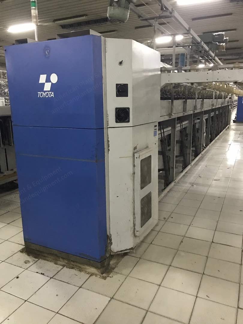
Description Overview Toyoda high-speed simplex fly-frames model FL100 Year 1997 120 spindles each Right hand drive (headstock positioned at right hand when facing flyer) Main Specifications Number of spindles per machine: 120 spindles Staff length: 440 mm Number of spindles per staff: 4 spindles Lift: 406 mm Nominal full bobbin diameter (actual): 152 mm (146 mm) Easier doffing device (flyer supported and driven at top flyer rail): included Fibre to be used: cotton Fibre length: 22 to 40 mm Yarn count to be spun: Ne 7, 13 and others Kind of yarn (combed or carded): carded Driving System 3 types of individual motors (motor built-in gear-end head - main (flyer + draft part) - bobbin and lifting) Push button switch control: for run, stop, and inching Soft start: by inverter Main revolution journals: mounted with ball bearings Drafting System 4-roller double apron d-type Roller stand inclination: 15 degrees Short bottom apron: Toyota standard Weighting arm: SKF PK1500-001938 Top roller load (kg/2 spindles): front 12 (9, 15), 2nd 20 (15, 25), 3rd 15 (10, 20), back 15 (10, 20) Cradle: SKF OH514-110 Radius and width: radius 34.5 mm, width 40 mm Tenser gauge (mm): green 6.5, blue 8.3, brown 11.3 Top apron: Toyota standard Bottom roller (front, 2nd, 3rd, back) diameter: 28.5 x 28.5 x 28.5 x 28.5 mm Bottom roller type (front, 2nd, 3rd, back): helical x helical x knurled x knurled Bottom roller finishing: multiple chromium coating, neck mounted with needle bearing and jointed with screw Top roller made by SKF: front, 2nd, and back = LP315-110, 3rd = LP317-110 Bare diameter: all 4 top rollers are 19 mm Covered diameter (front, 2nd, 3rd, back): 28 x 28 x 25 x 28 mm Rubber cot width (front, 2nd, 3rd, back): 39 x 39 x 40 x 39 mm Type of rubber cot: press fit type Bottom roller gauge: Armstrong, front to 2nd: 35-42 mm, 2nd to 3rd: 47-52 mm, 3rd to back: 45-52 mm Front collector, condenser, sliver guide: 7.0 mm, 15 mm, 17 x 4.0 mm Clearer and Suction System Clearer: positive intermittent revolving clearer with comb for top, bottom rollers Top clearer cover: with (open type) Bottom clearer cloth: individual type Pneumatic suction under clearer: for collecting bottom clearer waste by comb Exhausted air: floor Air suction: intermittent and continuous suction selectable Waste collecting device: standard (manual) Flyer and Bobbin Details Flyer spindle diameter: 22 mm Type of flyer: SL, slitless type Type of presser: stainless presser Flyer cap: standard (smooth front row, with groove back row) Driving systems: flyer shaft driven by timing belt, bobbin shaft driven by gear, flyer and bobbin driven by helical gear Shaping motion (mechanics and electronics): shaping motion by electric clutch Creel and Feeding Sliver feeding can: 508 mm (20) diameter x 1,067 mm (42) height Creel and rows of feeding rollers: for feeding of single sliver, stainless rows 6-line Rows of feed rollers for lifting up sliver: 5 Height of feed rollers: 1,700 mm Overall length from machine top to creel end: 3,830 mm Spinning Conditions Sliver to be fed: 420 gr/6 yds (card fibre) Roving to be delivered: 420 gr/30 yds, 350 gr/30 yds Total draft: 5.0, 6.0 Twist multiple: 1.1, 1.3 Twist per 25.4 mm: 0.849, 1.099 Flyer and delivery speed (mechanical): max. flyer speed 1,500 rpm, delivery speed 60 m/min Flyer and delivery speed (practical): max. flyer speed 1,200 rpm, delivery speed 50 m/min Electrical and Motor Specifications Winding up, lifting, suction and blow motor: 3.7 kW 4P, 2.2 kW 4P, 3.0 kW 4P Indicator, auto counter: 5-figure, 3 shift indication, 5-figure indication unit Tower-shaped signal lamp: gear-end side Special Attachments Included Automatic tension controller by micro-computer Irregular roving preventing device Package shoulder collapse preventing device Miss-bobbin donning prevention device Function panel Flyer speed control device (inverter) Main gearing in oil bath (new type) Automatic grease supply device for draft gearing Automatic roving positioning device for re-start Set-length stop and constant-position stop Options Included Stop motion upon roving breakage at middle part of package Safety cover in front of flyer Automatic lubrication device for flyer and bobbin gear Luwa BS-type traveling cleaner Included Items and Documentation Remaining available spare parts Approximately 5,000 pieces roving bobbins Floor plan diagrams, electrical diagrams, instruction manuals, and other diagrams, parts lists in English are included Sliver cans will be included in sufficient quantity (as which will fit into empty space of container while loading these 2 machines)