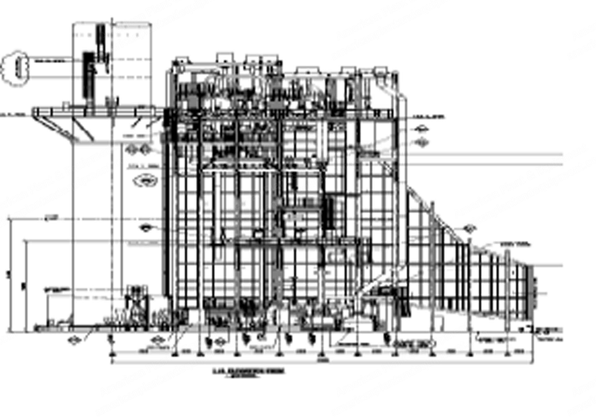
Power block equipment for 50 Hz gas based combined cycle power plant
Quantity: 2 sets
Item 001: Gas Turbines with Mandatory Spare Parts
Manufacturer: GE
Model: MS9001-FA
Year: 2010
Quantity: 2
Item 002: Steam Turbine and Auxiliaries
Manufacturer: GE
Model: D11
Year: 2011
Quantity: 1
Item 003: Heat Recovery Steam Generators and Auxiliaries System
OEM: M/S CMI-EPTI, USA
Year: 2011
Quantity: 2
Item 004: Condenser and Auxiliaries
Year: 2011
Quantity: 1
Electrical Equipment and Systems
Item 005: Gas turbine generator
Rating: 15.75 kV/400 kV
Brand: M/S Hyundai
Year: 2011
Quantity: 2
Item 006: Steam turbine generator
Rating: 15.75 kV/400 kV
Brand: M/S Hyundai
Year: 2011
Quantity: 2
Item 007: Generator circuit breaker
Brand: ABB
Year: 2011
Quantity: 3
Item 008: Unit auxiliary transformers
Brand: AREVA
Rating: 15.75/6.6 kV
Year: 2011
Quantity: 3
Technical Information Document for 750 MW Combined Cycle Power Plant Equipment – Part A: Gas Turbine Generator
Gas turbine generator systems overview
Gas turbine: MS9001(FA) supplied by General Electric (GE), single shaft, bolted rotor with generator connected at compressor or cold end, axial exhaust optimal for combined cycle
Compressor section: 18-stage axial flow compressor with modulating inlet guide vanes, interstage air extraction for cooling, sealing, and surge control
Compressor rotor: forward stub shaft with stage zero blades, blade and wheel assembly for stages 1-16, aft stub shaft with stage 17 blades, blades inserted into broached slots
Compressor blade design: airfoil shaped, designed for high blade tip velocities, made from corrosion resistant material
Compressor stator: inlet casing, compressor casing, and compressor discharge casing
Compressor casing: contains stages zero through 12, extraction ports for bleeds and cooling air
Compressor discharge casing: contains 13th through 17th stage stators and exit guide vanes, supports first-stage turbine nozzle and combustion components, air extracted for fuel system purge, inlet bleed heat, compressor surge control, and inlet filter pulse cleaning
Turbine section: three-stage, converts hot pressurized gas to mechanical energy, includes turbine rotor, shell, exhaust frame, diffuser, nozzles, diaphragms, stationary shrouds, and number 2 bearing assembly
Turbine rotor: forward shaft, three turbine wheels, two spacer wheels, aft shaft with number 2 bearing
Turbine bucket design: first-stage uses forced air convection cooling with serpentine passages, second-stage cooled via radial holes by shaped tube electromechanical machining, third-stage uncooled
Turbine stator: turbine shell and exhaust frame, horizontally split for maintenance
Turbine shell: provides internal support and positioning of shrouds and nozzles, includes borescope ports
Exhaust frame: bolted to aft flange of turbine shell, outer and inner cylinder interconnected by radial struts, supports number 2 bearing
Turbine nozzle design: three stages of stationary blades, air cooling to all three stages, first and second stages use film, impingement, and convection cooling, third stage uses convection only
Bearings: two radial bearings and one dual direction thrust bearing, located in two housings (inlet and center of exhaust frame), pressure lubricated by main lubrication oil system
Combustion system: reverse flow, multi-chamber can annular design, chambers arranged around compressor discharge casing, connected by crossfire tubes
Dry low NOx (DLN) combustor: DLN 2+, single stage, multi-mode, capable of operation with natural gas
Combustion liners: cylindrical, discharge air flows along outside guided by flow sleeve, backside cooling, thermal barrier coatings applied
Transition pieces: direct hot gases from liners to turbine nozzles, circular inlet, annular segment exit, seals at connections
Spark plugs: two electrode spark plugs in different chambers, ignite at firing
Request a Quote
✓
Request sent
Thank you, our team will reply to you shortly.
Direct access to our team
Email American Plant & Equipment
Tell us what you want to buy, source, finance, or sell. A machinery specialist will follow up with you.
✓
Thank you. Your request is with the American Plant and Equipment team.
A machinery specialist will follow up with you.
Machinery updates
Subscribe to our email list
Tell us which industries you follow and we will send you the machines that match.
✓
You are on the list.
We will email you when machines that match your interests come in. Unsubscribe from any message.