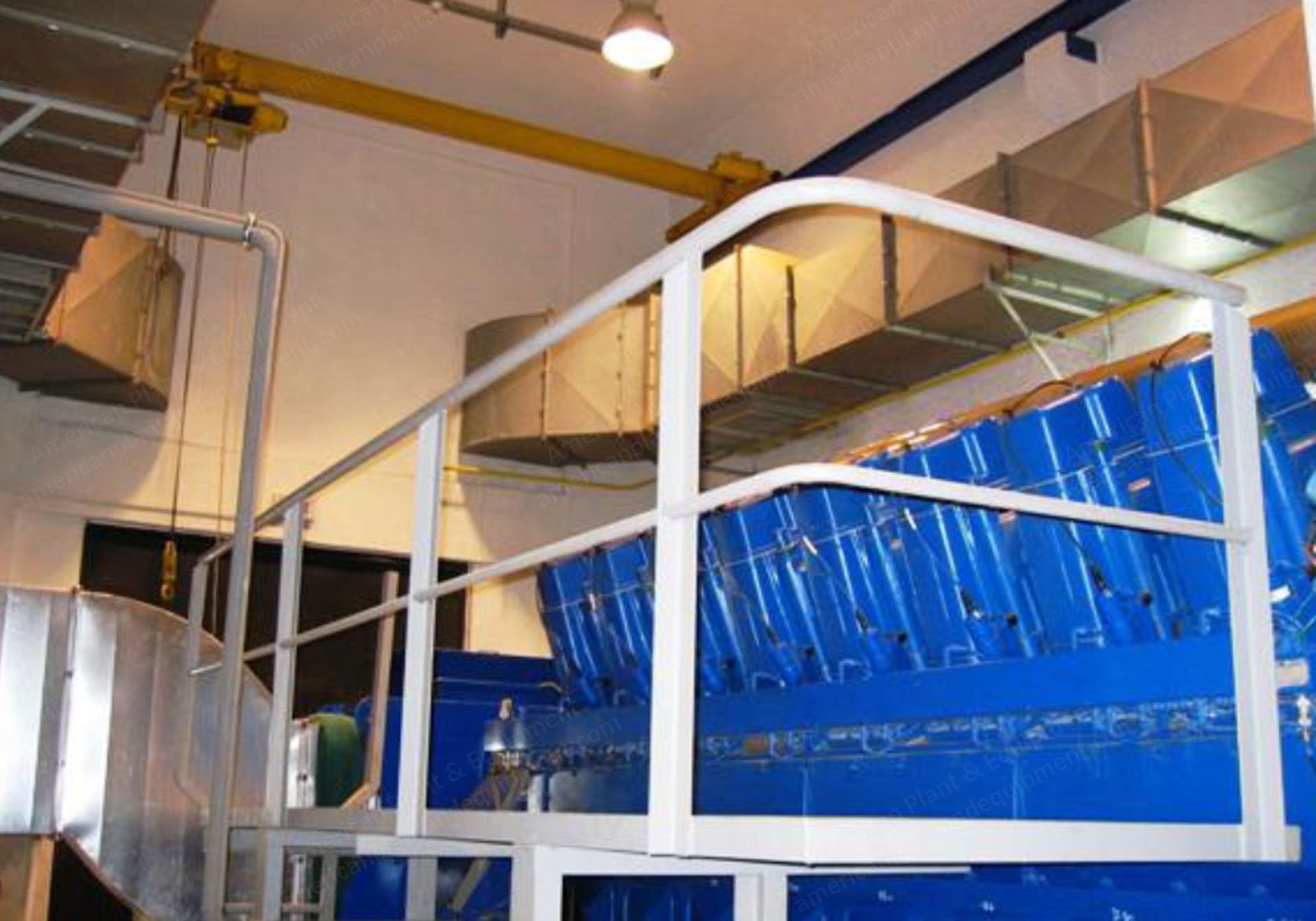
Deutz, TBG 632 V 16, 7.8 MW, Gas Engine Based Power Plant, 1000 RPM
Scroll to zoom
100%
Description
Overview
Two MWM Deutz make 3.9 MW each type TBG 632V16 gas engine generator sets.
The plant consists of two Deutz (MWM) engines, model TBG 632 V 16 operating by natural gas.
Before the connection to the gas regulator group of each motor, the natural gas passes through a newly installed measurement and regulation system that filters and reduces the pressure to adapt it to the motor requirements.
The data of the Otto cycle gas engine, with lean mixture combustion, turbo charger.
Specifications
Brand: Deutz TBG 632 V 16.
Unit power: 3,916 kWe.
Gas consumption: 9,336 kW at 100% loading tolerance 5%.
Cylinders and configuration: 16 V.
Rotational speed: 1,000 rpm.
Electrical efficiency: 41.4%.
Thermal efficiency: 44%.
Air flow inlet approx.: 20,079 kg/h.
Exhaust gas flow approx.: 20,897 kg/h.
Gas temperature: 467 °C.
Each engine operates a generator of 4.850 kVA electrical output.
The current of each generator is sent to apart 11 kV set-up transformer.
Condition
The installation has running time of the engines of 46,300 h and 45,300 h hours respectively.
Thermal Utilization - Steam Generation
The exhaust gas from engines were directed to heat recovery steam generators (boilers) that produce 3 t/h saturated steam at 7.5 bar using the heat produced by the exhaust gas.
Maximum steam flow with exhaust gases from the engine: 3 t/h.
Registered pressure: 10 bar.
Normal operating pressure: 7.5 bar.
Steam quality: 3,010 kg/h.
Exhaust gas recovery flow: 20,897 kg/h.
Gas temperature of engines: 467 °C.
Feed water temperature: 95 °C.
Eco-outlet temp. with exhaust gases: 163.8 °C.
Thermal Utilization - Hot Water
The thermal energy from the HT and LT coolant circuits of the engine were also used to produce 2,132 kWh/engine.
The total heat balance of the cogeneration plant is as follows: steam production from exhaust gases at 7.5 bar 3 t/h per engine; hot water production.
Therefore the recovered heat during the cogeneration process is: recovered heat exhaust gases 1,739 kWth/engine; recovered heat cooling water 2,132 kWh/engine; total heat used 3,871 kWh/engine.
Total Annual Energy Balance
Running hours per engine 8,000 h.
Power 2 x 3,916 = 7,832 kWh.
Electricity generation 62,656,000 kWh.
Fuel consumption 2 x 9,336 x 8000 = 149,376,000 kWh.
Steam produced 2 x 3 x 8,000 = 48,000 t/year.
Used heat 61,936,000 kWh.
Electrical Installations
The cogeneration electrical system entails two 4.850 kVA alternators, both at 11 kV 50 Hz.
Engines are connected to the grid by means of a step-up transformers.
For the electrical power supply of the equipment within the cogeneration plant, there is an auxiliary switchboard.
This distribution board to auxiliary service supplies the following equipment: boiler control panels, pumps and ventilators, process control panel, control panel of the engines, crane bridge, air coolers, ventilation fans, lighting, etc.
Scope of Supply - Engines and Generators
Engines (x2) - Deutz AG (MWM) TBG 632 /TCG 2032 V 16 3,916 kWe / model year = 2003.
Generators (x2) - AVK DIN 256 I/6 4,850 kVA – 255 A / model year 2003.
Scope of Supply - Pumps and Heat Exchangers
Air inlet pumps (x2) – Allweiler AG / NB 32-200 12 m³/h, H0020= 11 mt, 1.1 kW, 1,450 d/d, model year 2004.
Plate heat exchangers (x2) - GEA UT 40 CDL-10.
Oil tanks (fresh and waste).
Oil heat exchangers (x2) - GEA type NT 150 L CD-10.
Intercooler pumps (x2) - Allweiler AG / NB 50-160 65 m³/h, H = 30 mt, 11 kW, 2900 d/d, model year 2004.
Jacket water pumps (x2) - Allweiler AG / NB 65-200/2 113.7 m³/h, H = 38 mt, 11 kW, 2900 d/d, model year 2004.
Hot water of customer side (seconder side) jacket water pumps (x2) - Allweiler AG / NB 65-125 85.2 m³/h, H = 16 mt, 7.5 kW, 2900 d/d, model year 2004.
Compressors (x2) - Hatlapa L35/ 31.5 m³/h / 30 bar / 6.6 kW /model year 2004.
Air tanks (x2) - Romer GmbH / 30 bar, 2,000 lt, model year =2004.
Scope of Supply - Boilers and Equipment
Boilers (x2) capacity = 1,739 kW/h, operation pressure = 7.5 bar, project pressure = 10 bar, model year = 2004.
Feeding pumps (x4) - KSB WKL-32-5 / 3.6 m³/h, H=100 mt, 2,900 d/d, 3 kW, model year = 2004.
Heat exchanger of dearator GC16, model year 2004.
Economizers.
By-pass valves (dampers).
Stacks.
Scope of Supply - Mechanical Equipment
Storage tank for hot water (40 m3).
Silencers.
Table coolers for HT circuits (x2) - HT 1,967 kW (2 kW x 12 fans), model year = 2004.
Table coolers for LT circuits (x2) - LT 330 kW (2 kW x 6 fans), model year = 2004.
Ventilation fans (x4) – AKS 1902 ASP type, 50,000 m³/h, 18.5 kW, model year = 2004.
Exhaust silencers.
Engine’s room ventilation pre-heatings.
Cranes.
Air compressors and compressed air tanks.
Pumps, valves, etc.
Platforms.
Ventilation canal’s.
Scope of Supply - Electrical
Control and LV: low voltage panel: MCC; Deutz engine control panels (TEM); local Deutz engine control panels; auxiliary systems control panels; (Kuhse) fire-fighting and gas detection panel; boiler control panels; lighting panels.