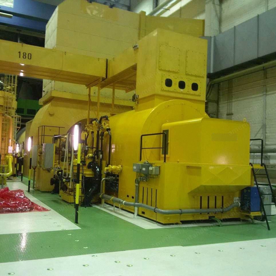
Alstom, BBC GT13B, Gas Turbine Power Plant, 252 MW, 50 Hz
Scroll to zoom
100%
Description
Overview
Complete power plant including Siemens master control station
2 gas turbine groups consisting of 2 gas turbines
Approximately 500 operating hours (used emergency supply)
Fully operational, as good as new
Immediately available
Introduction
The gas turbine power plant (GTPP) consists of four fossil-fueled (fuel: light heating oil) gas turbines made by Brown Boveri (later ABB and now Alstom), type BBC GT13B, with an individual capacity of 63 MWel and a total capacity of 252 MWel
The GTPP was originally intended as a backup system to supply emergency power to the adjoining nuclear power plant and to cover load peaks in the surrounding electricity grid
It is connected to the 50 Hz transmission grid through the public network switchgear
The plant was designed and built as a fast-start plant that can be brought up to full-load operation within approximately 5 minutes
It is currently changed to diesel fuel operation but can be installed as gas power plant with newest technology updated by Siemens engineers with Siemens technology
The equipment has approximately 500 operating hours and is fully operational
Technical Description
Layout of the plant: It is installed in its own separate turbine house, along with the necessary associated auxiliary systems
Each pair of gas turbine sets is arranged in parallel and connected to a common exhaust stack
The two gas turbine groups are located on opposite sides of the central corridor through the turbine house, with their generators facing each other
The turbine house level is at the same height as the surrounding grounds
A gas turbine set essentially consists of a combustion chamber, a gas turbine (compressor and turbine), a generator, and an exciter unit
There is a starter unit for each pair of gas turbines
Access to the plant: The plant and its individual components are easily accessible
The turbine platform is at the same height as the turbine house
The shared turbine house crane, with a load capacity of 50 t, can be moved over all parts of the plant without hindrance, which is advantageous for installation and dismantling activities
The intake housings for the individual compressors are arranged accordingly below the turbine house crane level, with inlets routed sideways to the walls of the turbine house
The central corridor of the turbine house between the turbine groups leads directly to the building entrance, which is large enough to accommodate heavy load vehicles suitable for the GTPP
Main components and interfaces to other components: A gas turbine set consists of a combustion chamber, a gas turbine (compressor and turbine), a generator, and an exciter unit, along with all associated control devices, control valves and stop valves
The generator coolers are integrated into the housings of the individual generators
Each plant also has an oil supply system for control, lubrication and shaft lifting, including the associated valves, oil pumps and tanks
Interfaces include: exhaust outlet of the gas turbine after the exhaust diffuser and exhaust line to the connection flange at the inlet to the exhaust stack (interface is the sliding collar at the bottom of the stack)
On the fresh air side before the compressor inlet on the connection frame of the compressor intake housing at the outlet of the intake housing after the intake filter, above the gas turbine set
Fuel supply from the main valve of the fuel line and the following control valves for the combustion chamber (the fuel line after the buffer tank belongs to the plant, along with the return line)
Cooling water inlet and outlet before each generator cooler, at the respective stop valve
Electrical handover after the electrical pass-throughs and generator branch lines above the turbine sets, before the busbars of the common central transformer system (outside the building)
The overall plant also includes: the starter units, the central compressed air system, the electrical switchgear for operation of the plant, and the central control system equipment (Siemens T3000) and control console
The oil supply system, including the bearing oil tank and bearing oil cooler, is part of the plant
The fuel control cabinet for controlling the plant and the fuel pump unit
The central transformer after the electrical busbars is not part of the sellable GTPP system
The intake silencers and exhaust silencers, including housings, belong to the building component
Mode of Operation and Condition of the Overall Plant
The GTPP was operated as a peak load system until 2013
After that it was operated as an on-call emergency system (short-term load), resulting in a further reduction in the operating hours per calendar year
The plant is visually in very good condition
It is clean and well maintained, and the necessary labeling of components and valves is in perfect condition
There are no externally visible signs of leakage
There has been no foundation settling of the overall plant over the entire life cycle to date, so there has been no cause for internal misalignment
This can also be seen in the good to very good vibration characteristics of the plant
The measured vibration data of all units yielded very good vibration values in the lower region of zone A
However, there is no constant vibration registration by the control system, only vibration monitoring at the individual bearing blocks
There have also been no external lightning strikes in the nearby electrical grid over the entire life cycle to date, so the probability of concealed internal damage to the generators is negligible
Due to the mode of operation (peak load) and the very low number of equivalent operating hours, the plant is in very good condition with low wear
Request a Quote
✓
Request sent
Thank you, our team will reply to you shortly.
Direct access to our team
Email American Plant & Equipment
Tell us what you want to buy, source, finance, or sell. A machinery specialist will follow up with you.
✓
Thank you. Your request is with the American Plant and Equipment team.
A machinery specialist will follow up with you.
Machinery updates
Subscribe to our email list
Tell us which industries you follow and we will send you the machines that match.
✓
You are on the list.
We will email you when machines that match your interests come in. Unsubscribe from any message.