Never installed or used; crated and sitting in warehouse.
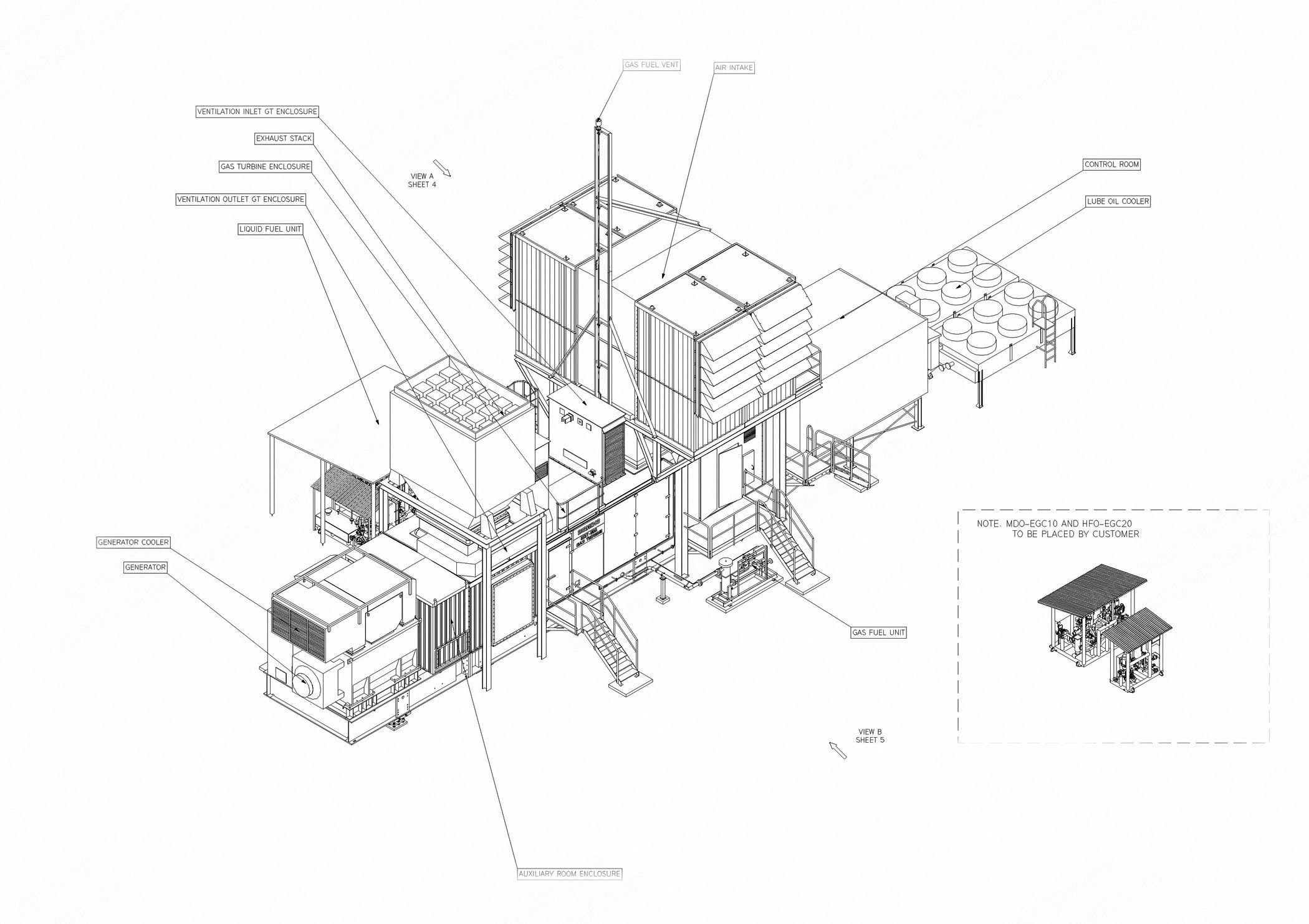
Siemens model SGT-500 gas turbine power generation for inland applications.
Nominal rating of 19.1 MW at 60 Hz and 13,800 V.
Scope of supply forms a separate unit within terminal points; utilities/consumables such as auxiliary power, fuel, water, washing detergent, instrument air, lubricating oil and grease are excluded.
Alternative configurations are available.
Gas Turbine Equipment
Three-shaft designed core engine arranged for hot end drive and meeting electrical ISO conditions.
Compressor inlet casing and inlet bell mouth casing.
Gas generator.
10-stage low pressure compressor and eight-stage high pressure compressor.
One-stage high pressure turbine and two-stage low pressure turbine.
Pneumatically actuated bleed air extraction during start-up and shutdown.
Seven can combustion chambers.
Seven dual fuel burners prepared for possible later conversion to dual fuel duty.
Compressor turbine stator.
Power turbine stator.
Power turbine with a constant speed of 3600 rpm.
Power turbine exhaust casing with exhaust diffuser.
Three stage power turbine rotor.
Accelerometer type vibration probes.
Combustion Air Inlet System
Filter house in painted carbon steel with service platform and ladder.
Back to back static filter system with one-stage pulse filter, filter class F9.
Support structure for filter house.
Silencer.
Inlet chiller including house, supports and connection flanges.
Exhaust Gas System
Sheet metal exhaust casing.
Vertical exhaust stack including bellows, transition, silencer, insulation and support.
Insulated silencer in the exhaust duct, stainless steel in baffles and shield, external thermal insulation covered with alu-zink on the outside.
Support structure in carbon steel for the exhaust silencer.
Base Frame for Gas Turbine
Welded I-beam base frame for the gas turbine driver unit with drop in lubricating oil tank.
Equipped with rails for rolling of gas generator out of the enclosure for maintenance; additional rails installed for sliding gas generator sideways out from the enclosure.
Fixed three-point support between base frame and foundation.
Gas Turbine Enclosure
Enclosure for weather and noise protection equipped with ventilation, main and emergency lighting and external stairs and walkways.
Maintenance opening on selected side, and internal walkways for service.
Ventilation for Gas Turbine Enclosure
1 x 100% AC driven fan creating atmospheric overpressure in gas turbine enclosure.
Air filter for high dust load.
Pressurized Liquid Fuel System
Pressurized liquid fuel system located outside gas turbine enclosure; liquid fuel according to Siemens specification E243008E.
Heavy fuel oil booster module including heavy and light fuel oil inlet, pressurized service tank, heating loop including circulating pump with filter, heat exchanger and viscosity meter, and high pressure fuel oil injection pump.
Heavy fuel oil forwarding pump skid including 1 x 100% speed controlled heavy fuel oil forward pump and 1 x 100% filter with differential pressure transmitter.
Light fuel oil forward pump skid including 1 x 100% speed controlled light fuel oil forwarding pump.
Enlarged fuel dosing system.
Gas Fuel System
Gas fuel system including gas control valve, pressure safety valves and purge air connections, all with possibility to operate in gas fuel mode or in mixed fuel mode.
Starting System
Combined low voltage starting and barring motor mounted on low pressure compressor inlet casing.
SSS-type semi rigid overrunning clutch.
Lubricating Oil System
System common for driver, gear box and electrical generator.
Carbon steel tank with sub-merged oil heating.
One AC driven pump and one DC driven emergency pump as back-up.
Electrical heaters.
2 x 100% oil filter with possibility to switch filter during operation.
AC driven oil mist fan with filter to obtain sub pressure; DC driven fan as back-up.
Piping downstream filter in stainless steel.
Cooling and Sealing Air System
Instruments and components for standard cooling and sealing air system.
Washing and Cleaning System
Washing system for turbine compressors.
Washing system for turbines.
Water wash trolley.
Air Inlet Chiller System
2 x 50% chiller coils in carbon steel with surface treatment class C4 both inside and outside.
Chiller frame material in AISI304L; pipes in copper; chiller lamina material in ALMg2.5 (PED requirement).
Mist eliminators in PPTV.
Distribution pipe material in AISI304L with DN350 connection.
Drain pipe DN100 connection.
Electric Generator Equipment
Air cooled AC generator of salient pole brushless type.
13.8 kV, three phase, four pole, 60 Hz AC generator of salient pole brushless type; power factor 0.8.
Generator bearing temperature detectors and accelerometer vibration detectors.
Manufacturer's standard works acceptance test.
Class F insulation with class B total temperature.
Generator control panel containing generator metering equipment and electrical protection.
Automatic voltage regulator.
Line and Neutral Cubicle
Neutral earthing resistor.
Synchronizing Equipment
Automatic and manual (semiautomatic) synchronizing system for two circuit breakers: the generator circuit breaker and one additional breaker; system provided with a synchronizing by-pass switch for breaker closing against a dead bus.
Frequency/load control.
Main Gear and Couplings
3600/1800 rpm speed reduction gear of double helical design; high speed side: flexible coupling; low speed side: internal quill shaft with stiff flange coupling.
Enclosure for Main Gear
Enclosure over the gear system.
Auxiliaries
Anchor bolts for auxiliaries such as stairs, platforms, coolers, fuel systems etc.
Gas Detection System
Enclosure provided with extended gas detection system to detect leakages of vaporized fuel.
Fire Detection and Extinguishing System
Fire detection and extinguishing system for the gas turbine room.
1 x 100% CO2 discharge for fire protection.
Central fire suppression unit for alarm and automatic extinguishing.
Manual release buttons located outside each door of the gas turbine room.
Extinguishant release audible and visible alarms.
Extinguishant system distribution pipework, valves and nozzles.
Electrical and Control Equipment
Local equipment room: electrical and control module including lighting, HVAC and external stairs and platforms.
Motor control center: MCC including LV distribution of withdrawable unit design supplying all consumers.
Control system: microprocessor based control, supervision and protection system with PC based operators station; application software in controllers are battery backed-up for two months; license for control system programming included in operator station.
Package protection system built around a failsafe EC 61508 SIL proven safety controller.
The most important signals work according to the principle of 1oo2.
Main control and monitoring of the gas turbine contains systems and programs to perform both open and closed loop control.
Request a Quote
✓
Request sent
Thank you, our team will reply to you shortly.
Direct access to our team
Email American Plant & Equipment
Tell us what you want to buy, source, finance, or sell. A machinery specialist will follow up with you.
✓
Thank you. Your request is with the American Plant and Equipment team.
A machinery specialist will follow up with you.
Machinery updates
Subscribe to our email list
Tell us which industries you follow and we will send you the machines that match.
✓
You are on the list.
We will email you when machines that match your interests come in. Unsubscribe from any message.