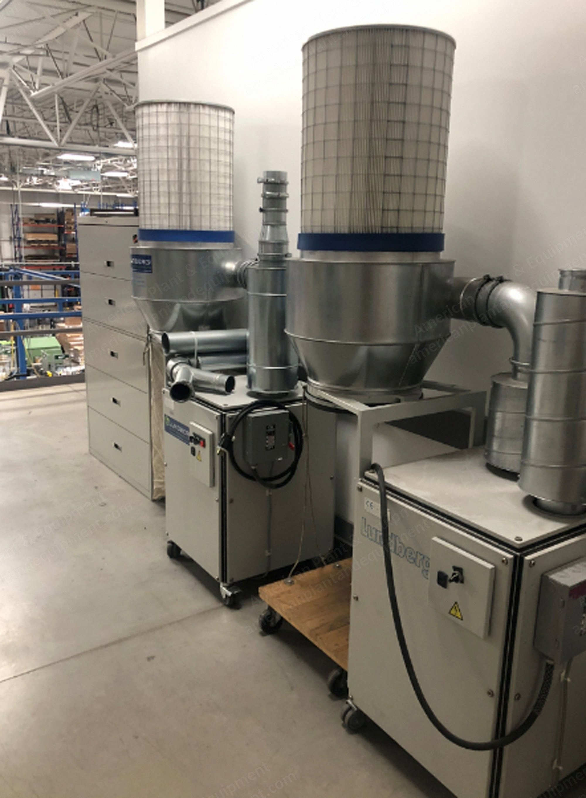
Lundberg, Compact GR 80, Granulator and Ventilator, 1.1kW Ventilator, 0.55kW Granulator, 125mm Piping
Scroll to zoom
100%
Description
Technical Specifications
Granulator: GR80
Ventilator: FT24
Power: 3 x 400 V, 50 Hz
Amperage: 4 A
Fuse: 10 amp
Piping: ø125 mm
Noise level: max. 75 dB(A)
Surface treatment: powder lacquering RAL 7035
Exact technical specifications for the granulator and ventilator can be read in their own operating instructions.
Installation And Fitting
When pipes are fitted on the compact, the suction pipe should be fixed with a snap clamp with a screw under the cabinet.
The blow-off pipe should be fixed with bolts on the fan and should project through the cabinet.
Both pipes should be of minimum one metre length.
A silencer should also be fitted on the blow-off side to reduce the noise level.
Maintenance
The filters shall be cleaned once a week with a vacuum cleaner.
The combi should not be maintained in any other way.
It is good practice to undertake general cleaning of the combi to remove any dirt that has accumulated on the motors.
Repair
When carrying out any repair of the granulator and fan, see the relevant instructions for use.
Electrical Connection And Wiring
The unit should be connected to a 3-phase mains supply with a neutral conductor, 230/400 V AC, 50 Hz.
The fuse should be max. 10 A.
When the unit is operated at full load, the absorbed current of the GR80 is In = 4 A.
Documentation
Table layout: diagram 21055-A1 shows the arrangement of components in the table lid and on the table base plate respectively.
Key diagrams: the unit’s wiring is shown in diagram 21821-01.
Parts list: the parts list specifies the diagram code, make, and type number of the used components.
List Of Parts For Compact GR80
1 cabinet GR80 compact
1 ventilator FT24
1 granulator GR 80 U
1 outlet
1 1.1 kW el-motor
1 0.55 kW el-motor
1 bend
1 bearing for granulator motor
2 snap ring
Granulator GR 80 U Specifications
GR 80 U has been developed for continuous cutting of paper and plastic, e.g. edge trimming of roll cutters and printing machines.
The granulators can be built into both new and existing pipe systems by the use of quick-connectors.
Standard: granulator GR 80 U with 0.55 kW motor, 3x400 V, 50 Hz.
Accessories: integrated frequency converter for 500-4000 rpm, oil system, transition piece for integration into other pipe sizes.
Granulator marking: type GR 80 U, marked with an arrow showing direction of rotation and through-flow direction.
Granulator housing: cast iron.
Motor: 0.55 kW type M71
Power: 3 x 400 V, 50 Hz
Nominal amperage: 1.2 A
Fuse: 10 amp
Rotor: hard-metal blades
Piping: ø125 mm
Transmission: direct coupling
Weight: 20 kg
Weight without motor: 12.5 kg
Surface treatment: powder lacquering
Noise level: 60 dB(A)
Granulator Installation And Fitting
When pipes are fitted on the granulator, a fixing collar with screws should be used so that the pipe can only be removed with the aid of tools.
The pipes and a support plate for the motor can retain the granulator.
When pipes and machine are fitted and dismantled, the motor must be disconnected from the power supply, which can be done with a safety cutout interlock switch.
Before the motor is energised, a one-metre pipe must be at least provided on each side of the granulator for reasons of safety.
Granulator Maintenance
The manufacturer recommends the bearings and coupling carrier plate being renewed after max. 3200 hours’ operation.
It is also recommended to grind the rotor blades and fixed blades on the same occasion.
See under “replacing spare parts”.
Adjustment Of The Fixed Knife
The knives are adjusted by the manufacturer; this instruction shall only be used after repairs.
Check that the screws (pos. 3) are tightened.
The screws (pos. 2) are turned till “hand tight”.
The screws (pos. 4) are tightened sufficiently so that the fixed knife (pos. 1) is just touching the rotor blades. During tightening the rotor is turned manually and it must be checked that the resistance against turning is equal for all rotor knives.
The screws (pos. 5) are tightened and the position of the knives is checked by feeding a thin piece of paper down between the knives, while the rotor is turned manually. It must be checked that each rotor knife is cutting over its total length. The screws (pos. 2) are tightened and the check is repeated. If the knives are not cutting evenly, adjustment is made by means of screws (pos. 4 and 5).
The blower is turned off at the electric control unit and the granulator is turned on. If the granulator is making noise, the screws (pos. 4) are loosened and the screws (pos. 5) are tightened until the noise stops. To avoid damaging the knives, adjustment while running must be done with extreme care and therefore the screws (pos. 2) must not be loosened.
Replacing Spare Parts For Granulator
When spare parts are being replaced, it is recommended they be replaced by the manufacturer.
If this is not possible, these instructions should be followed: the motor should be disconnected from the power supply.
When parts are being replaced inside the granulator, the motor and granulator should be separated (see page 9) and the coupling and coupling carrier plate taken out with the motor.
The locking ring is first removed. The bearing housing, rotor, and bearings can then be removed altogether.
When new bearings are to be fitted, pressure should be applied to the inner race to get the bearings into position on the rotor. The bearing housing is then mounted so that rotor, bearings, and housing form a single unit.
The unit is carefully put in place so that the bearings are not overloaded. The locking ring is then fixed in position.
The granulator and motor can now be assembled after it has been first checked that the coupling and coupling carrier plate are properly seated.
The fixed blades should be replaced from outside (see page 10): the blade can be taken out by removing the cover plate, adjustment plate, and screw holding the blade in place.
Important: when any part of the machine whatever has been replaced, the fixed blade should be adjusted according to the relevant instructions.
List Of Parts For Granulator GR 80 U
1 0.55 kW el-motor
4 Allen screw
1 distance piece
1 snapring
1 coupling
1 coupling disk
1 coupling
2 bearing
1 rotor complete with blades
1 housing
1 bearing housing
1 housing
2 washer
2 washer
2 Allen screw
1 fixed knife
1 flange
2 pointed screw
5 Allen screw
4 washer
4 Allen screw
1 cover
2 Allen screw
Ventilator FT24 Specifications
Type FT24 has been developed for sucking.
Request a Quote
✓
Request sent
Thank you, our team will reply to you shortly.
Direct access to our team
Email American Plant & Equipment
Tell us what you want to buy, source, finance, or sell. A machinery specialist will follow up with you.
✓
Thank you. Your request is with the American Plant and Equipment team.
A machinery specialist will follow up with you.
Machinery updates
Subscribe to our email list
Tell us which industries you follow and we will send you the machines that match.
✓
You are on the list.
We will email you when machines that match your interests come in. Unsubscribe from any message.