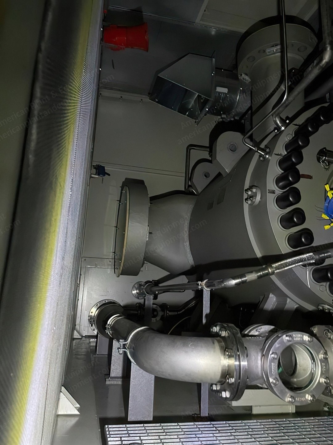
Siemens, SGT600, 2010, Gas Turbine, Dual Fuel, 60 Hz
Scroll to zoom
100%
Description
Overview
Siemens SGT600 gas turbine – new, 4 units available.
Rated at 25.2 megawatts each.
Year of manufacture: 2010.
Only 4 hours of testing under quality plan; control panel history shows zero operating hours.
Dual fuel capability.
Designed for gas pumping; can be used for generation if needed.
Units are 50/60 Hz capable (see notes).
Turbines manufactured in Finspång, Sweden.
Centrifugal gas compressors manufactured in Duisburg, Germany.
Stored in temperature and humidity controlled warehouse.
Scope Of Supply
Four identical SGT-600 + STC-SV (10-7-A) trains, each including: one skid for SGT-600 package and one skid for compressor package; common lube oil console for GT and compressor; lube oil air-cooler; fire and gas system for compressor and gas turbine; compressor fully enclosed with HVAC; compressor seal gas panel on skid; common unit control panel for GT and compressor including vibration monitoring and anti-surge controller; GT fully tested per API-616 and PTC-22 performance test; compressor mechanical run and performance tested per API-617 and PTC-10; gas turbine inlet air filter house and structure, inlet air ducts, ventilation, and exhaust silencer.
One SGT-600 spare core engine in metal pressurized container with nitrogen gas blanket.
One set of special tools for both GT and compressor.
Package in accordance with API 616, API 617, API 614, API 670, API 671, and all other industry practice specifications, and in accordance with Siemens standard designs, tests, and procedures.
Gas Turbine Engine
Two-shaft, low weight industrial type gas turbine with modular design; horizontally split compressor casing, upper case half lifted off for ease of maintenance.
Compressor inlet casing and inlet bellmouth casing.
All bearings of tilting pad type with directed mineral oil lubrication.
Optimum rpm: 7,700 rpm (3,850 rpm at 50% and 8,085 rpm at 105%).
10-stage axial flow compressor with two servo motor driven variable guide vane rings, electron beam welded compressor rotor and inner stator casing with vane carriers forming air flow path.
Two-stage gas generator turbine bolted to compressor rotor.
Thrust bearing #1 combined with radial journal bearing #1, located in inlet bellmouth casing; central casing containing radial journal bearing #2.
Two pneumatically actuated bleed valves for air bleed during startup and shutdown.
Ignition system including one removable high energy spark plug for startup burner.
Annular combustion chamber with internal thermal barrier coating; two optical flame detectors – one indicating flame at startup burner at ignition and one indicating cross ignition at startup; during operation both used as main flame detector.
Combustion chamber primary zone bypass arrangement with a motor operating six valves for emission control at part load.
18 DLE burners of second generation for gas fuel.
Two gas fuel manifolds: pilot and main.
Two stage power turbine with variable speed of 3,850-8,085 rpm; discs electron beam welded to shaft; counter clockwise rotation according to API 616.
Power turbine exhaust diffuser.
Manually operated drain valves at compressor inlet plenum, bleed cavities and at combustion chamber, power turbine and exhaust casings.
Radial journal bearing #3 located in the power turbine diffuser casing; one thrust bearing combined with one radial journal bearing #4 located in power turbine diffuser casing.
Insulation of gas turbine and exhaust casing for personnel safety and heat and noise attenuation.
12 x 1.5 mm instrument tubing in 316L stainless steel with double ferrule couplings for core engine.
Instruments with trip-function during operation have the following configuration: 1oo2 for exhaust gas temperature and flame detection; 1oo1 for axial displacement for gas generator and power turbine, inlet and outlet pressure and bearing vibration supervision; vibration transducers are of accelerometer type, one spare installed at each bearing #2 and #3; 2oo3 for gas generator rotating speed and power turbine rotating speed.
Compressor
Single shaft centrifugal compressor model STC-SV (10-7-A).
Barrel type compressor casing with side suction (left from coupling view) and top discharge.
Seven impellers.
Straight-through configuration: one suction, one discharge.
Dry Gas Seals
Compressor provided with two unidirectional dry gas seals with tandem with intermediate labyrinth configuration, with non-contacting carbon ring barrier separation seals.
Coupling And Guards
Dry, flexible element, disc type coupling.
Non-sparking coupling guard with drain connection.
Base Frames
Welded I-beam carbon steel base frames painted according to Siemens' standard coating system for onshore environments.
Multipoint support between base frame and foundation.
Driver skid: gas turbine and main auxiliary systems mounted on the base frame, including the integral lube oil console; stairs and walkways to access enclosure.
Driven skid: base frame common to the compressor and seal gas panel; non-sloped deck with non-skid surface.
Combustion Air Inlet System
Air inlet system including weather protection, filters and silencer.
Filter house in galvanized carbon steel with service platform and ladder.
Single side pulse clean filter system with two filter stages: class F7 pulse filters as first stage and static class E10 disposable high efficiency filters as second stage.
Support structure for filter house to ground level.
Low pressure drop inlet silencer with casing and baffles in stainless steel.
Inlet plenum in glass fiber composite with inspection window.
Combustion Exhaust System
Exhaust collector, transition duct and expansion joint, with external thermal insulation.
Exhaust collector orientation: side (right from coupling view).
Exhaust silencer.
Exhaust stack.
Exhaust emission sampling ports with insulation for personal protection.
Material of construction: exterior in carbon steel, internal hot gas path in SS 409, support structure in galvanized CS.
Enclosures
Driver skid: enclosure for weather and noise protection equipped with ventilation, main and emergency lighting and external stairs and walkways; the enclosure is an integral part of the machine safe.
Specifications
Capacity: 800 kW starting load
Request a Quote
✓
Request sent
Thank you, our team will reply to you shortly.
Direct access to our team
Email American Plant & Equipment
Tell us what you want to buy, source, finance, or sell. A machinery specialist will follow up with you.
✓
Thank you. Your request is with the American Plant and Equipment team.
A machinery specialist will follow up with you.
Machinery updates
Subscribe to our email list
Tell us which industries you follow and we will send you the machines that match.
✓
You are on the list.
We will email you when machines that match your interests come in. Unsubscribe from any message.