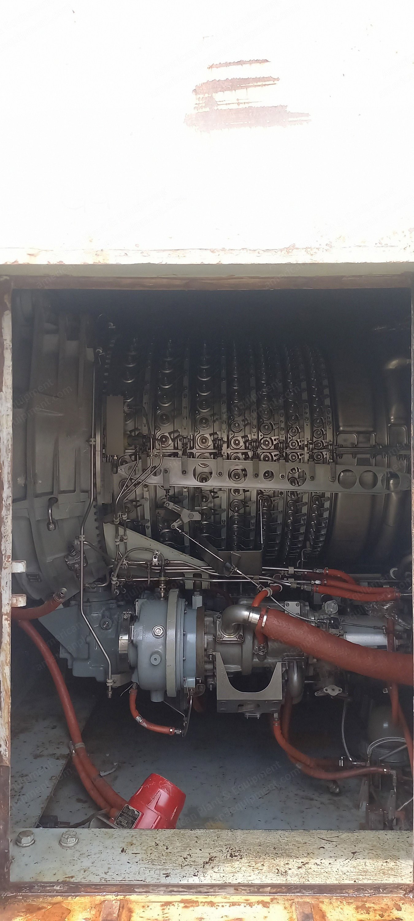
Description Component Breakdown List Bellmouth with water wash manifold Inlet center body (bullet nose) Gas generator Accessory drive gearbox On-engine fuel pump with filter assembly and piping to fuel manifold Liquid fuel nozzles Solenoid operated fuel shutdown valves Liquid fuel manifold Lube supply and scavenge pump Start motor with overrunning clutch Starter piping internal to module Start motor cooling medium line internal to module Igniter plugs with high voltage leads Ignition exciters VSV servo hydraulic pump with filter assembly and VSV actuators Compressor bleed air manifolds (CDP horns) Power turbine Power turbine speed sensor PT inlet gas average temperature thermocouple harness Power turbine accelerometer Compressor discharge pressure ports Fuel manifold pressure port Compressor inlet air temperature probe Lube oil supply pressure port Lube scavenge pressure port VSV position sensor LVDTs Passive chip detectors Lm2500 Gas Turbine Base Enclosure Structureborne noise/shock attenuating resilient mounts Gas turbine front and rear mount system Composite enclosure with 2 hinged side access doors (with windows) Exhaust collector with mounts Exhaust eductor nozzle Inlet FOD screen Barrier wall and seal Cooling air inlet ventilation damper Enclosure electrical heater Infra red flame detectors Module high temperature switches Internal incandescent module lighting set Compressor bleed air valve with internal module bleed piping Liquid fuel purge valve Door position switches Fuel metering valve Lube supply duplex filter with anti-static leak check valve High speed shaft shroud Air/oil separator with flame arrestor Air/oil separator vent piping to exhaust collector Module floor drains Safety rail and stanchion set Drain piping to oily waste systems SpecificationsUnit number: GG943