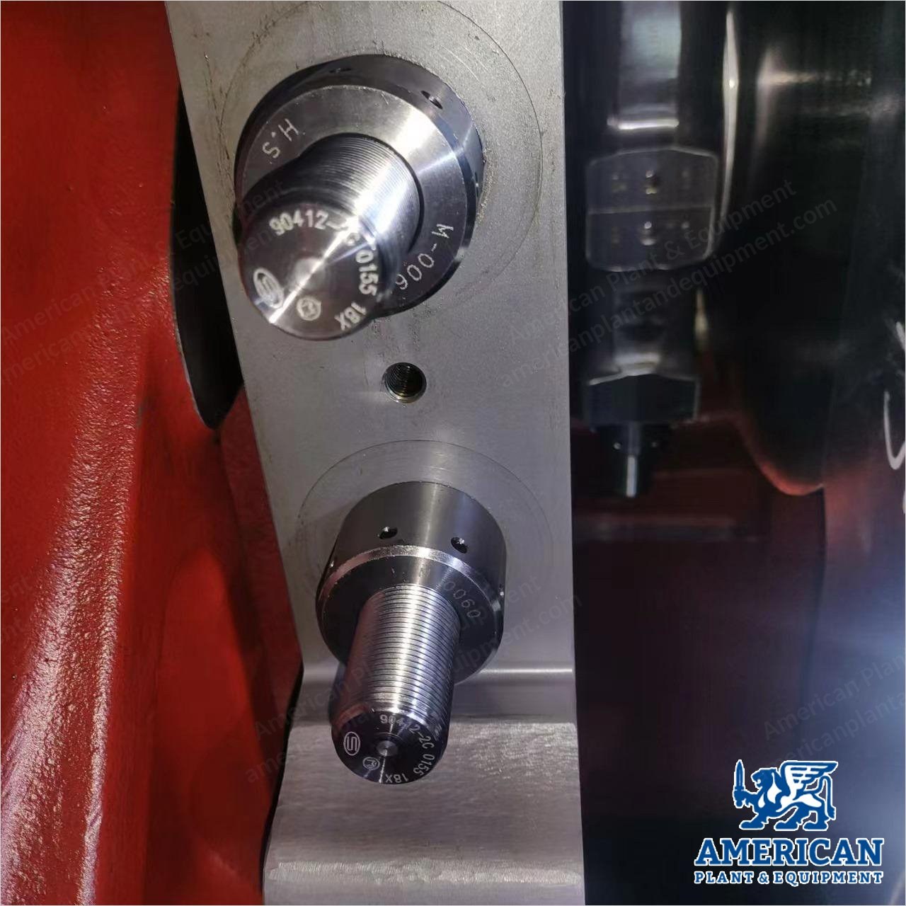
Description Overview Reference number: TT‑8483 Model: DOOSAN‑M.A.N. (Germany) 5L21/31 diesel generator set — new (surplus) Quantity: 2 sets (1 MW × 2 units) Fuel: HFO engine (can also run on diesel) Can run on HFO by adding the proper HFO conditioning and filtration accessories Rated voltage: 450 V Rated speed: 900 rpm Long‑term storage: by M.A.N. procedure Gen‑set nameplate: English, brass Mechanical arrangement: generator rigidly connected to engine on common base frame; base frame resiliently mounted to foundation Compliance & Environment Design standards (latest editions): ISO; GB; IEC; M.A.N.; manufacturer’s standards Design operation environment: ISO environment conditions Table 1 — rated ambient / ISO reference conditions Ambient air pressure: 1000 mbar (100 kPa) Ambient temperature: 25 ℃ Cooling water temperature (before CAC): 25 ℃ Relative humidity: 30 % If ambient conditions deviate from the above, power and consumption are to be modified per factory standard. Gen‑Set Performance (Table 2 — Main Performance Parameters) Nominal maximum continuous rating (engine flywheel): 1000 kW @ 900 r/min Output at generator terminals: 940 kW Frequency: 60 Hz Voltage: 450 V Power factor: 0.8 Engine (Prime Mover) Make: Doosan M.A.N. Diesel Engine type: 5L21/31 Configuration: four‑stroke, in‑line, 5 cylinders Firing order: 1‑2‑4‑5‑3 Crankshaft rotation: clockwise (viewed from flywheel) Air system: turbocharged & intercooled Engine Technical Data (Table 3) Rated power / speed: 1000 kW / 900 r/min Bore / stroke: 210 / 310 mm Max. combustion pressure: 21 MPa Mean effective pressure: 2.46 MPa Fuels: HFO (380 cSt @ 50 ℃), MDO, MGO (ISO 8217‑2017) Viscosity requirement at engine inlet: > 2 cSt when burning MDO/MGO/low‑sulfur fuel oil (S < 0.1 %) Shop test: running on 0# or ‑10# diesel oil SFOC @ 100% MCR: 193 + 5 % g/kWh Basis for consumption values: fuel LHV 42,700 kJ/kg; ISO 3046/1 ambient condition Lube‑oil consumption (MCR): 0.8 g/kWh Cooling water: add anti‑corrosion & cavitation additives; indices per engine spec Alternator (Generator) Manufacturer: Hyosung Type: HMD500‑08 Equipment: synchronous generator Alternator Technical Data (Table 4) Capacity: 1175.0 kVA Voltage / current: 450 V / 1507.5 A Frequency: 60 Hz Poles / speed: 8‑pole / 900 r/min Phase / power factor: 3‑phase / 0.8 lag Connection / duty: Y / continuous Protection: IP23 Insulation class: F Ambient temperature: 45 ℃ Temperature rise (A.F.): F / F Excitation voltage / current: 73.3 V / 6.4 A Bearing size (DE/NDE): Ø 140 mm Oil grade / quantity (DE/NDE): VG46 / 10 L Space heater: 1‑phase, 220 V, 400 W Weight: 5500 kg Rule: DNV Manufacturing date: 2012.03 Plate code: DGH10013 Dimensions & Weight (Table 5 — Per Set) Model: 5L21/31 A: 3959 mm B: 1870 mm C: 5829 mm H: 3183 mm Dry weight, gen‑set: 22.5 t Auxiliary Equipment (Table 6 — HFO Separator) HFO separator (used): Alfa Laval 305S‑11 — quantity 2 sets Scope of Supply — Basic Composition (8.1, Per Machine) Body assembly, front box, back‑end cover, oil pan, driving mechanism, cylinder, etc. Scope of Supply — Fuel System (8.2, Standard Supply) Safety filter, abs. 25 μm, with differential pressure indicator (1 set/engine), loose supply Injection pump, high‑pressure pipe, injection valve (each cylinder) Leakage alarm box for leaking oil, LAH42 Scope of Supply — Lubrication System (8.3, Standard Supply) Wet oil sump (inside base frame) Engine‑driven lube‑oil pump Lube‑oil cooler, plate‑type, stainless steel Pre‑lubricating pump, electrically driven Duplex filter; loosely supplied paper filter (1 set/engine) for project change Thermostatic 3‑way valve Lube‑oil centrifugal by‑pass filter Lube‑oil viscosity: SAE 40 Connections for lube‑oil to/from separator; lube‑oil overflow connection Scope of Supply — Cooling System (8.4, Standard Supply) HT and LT cooling water system (two‑string type) Engine‑driven HT water pump Cooling water automatic shut‑off valve (controlled by diesel lube pressure), 1 set/engine, loose supply Thermostatic 3‑way valve (HT system) Cooling water preheating branch automatic shut‑off valve (controlled by diesel lube pressure), 1 set/engine, loose supply Scope of Supply — Compressed Air System (8.5, Standard Supply) DC 24 V solenoid valve for local/remote start and emergency start valve Air starter for engine starting Manual turning device Turning tool (1 set per project): electric motor 3×380 V, 0.67 kW and starting box Scope of Supply — Combustion Air System (8.6, Standard Supply) Turbocharger Charge‑air cooler Water‑washing connection for turbocharger compressor Scope of Supply — Exhaust Gas System (8.7, Standard Supply) Gas outlet for vertical pipe connection after turbocharger Dry‑cleaning connection for turbocharger turbine Exhaust bellows between cylinder; insulated exhaust pipe between cylinder and turbocharger Scope of Supply — Governor System (8.8) Mechanical hydraulic governor (electron control) Scope of Supply — Control & Monitoring (8.9, Standard Supply) Alarm & shutdown sensors per Classification Society and M.A.N. standards M.A.N. control system: control module (engine control/monitoring/alarm) & indication module (engine/safety data) Safety system for overspeed, low lube‑oil pressure, high cooling‑water temperature, emergency stop Owner supply: two‑way sources power, uninterruptible DC 24 V Scope of Supply — Foundation (8.10, Standard Supply) Base frame on conical mounting; flexible pipe connections included All external connections with counter flanges, gaskets, bolts Service platform with handrails and steps Scope of Supply — Alternator (8.11, Standard Supply) Voltage 450 V; frequency 60 Hz; power factor 0.8; protection IP23; insulation class F Per‑Unit Nameplate Details (Table 7 — Units 1 & 2) Sub‑assembly: generator (both units) Manufacturer / brand: Hyosung Corporation Type: HMD500‑08 Key ratings: 1175.0 kVA; 3Ø/0.8 lag; 450 V/1507.5 A; 8P, 60 Hz; 900 r/min; Y/continuous; IP23; insulation F; ambient 45 ℃; temp rise F/F; excitation 73.3 V/6.4 A; space heater 1Ø, 220 V, 400 W; bearing Ø 140 mm; oil VG46, 10 L; weight 5500 kg Notes: rule DNV; mfg date 2012.03; country: Korea; plate code DGH10013; serial no. confidential Safety Labels (Generators, Both Units) Danger: hazardous voltage — may cause severe injury, death, fire, explosion, or property damage. Turn off and lock out all power before servicing or performing maintenance. Ground and protect per national and local codes. Installation, operation, and maintenance by qualified personnel. Rotating parts hazard — do not place hands/objects inside motor enclosure. Warning: failure to follow instructions may cause severe injury, death, fire, explosion, or property damage. Do not lift motor using lifting lugs when connected to additional equipment. Do not touch motor surfaces — may reach high temperature. Machined/pressed parts may have sharp edges; use proper protection. Optional Standard Spare Parts (Not Included — Table 8, Per Project) Customer must specify if these are required. No. 1 — cylinder head: valve seat ring, inlet; qty 2 No. 2 — cylinder head: O‑ring; qty 4 No. 3 — cylinder head: valve seat ring, outlet; qty 4 No. 4 — valve spindles & gear: conical ring; qty 6 No. 5 — valve spindles & gear: rotocap complete; qty 6 No. 6 — valve spindles & gear: spring; qty 6 No. 7 — valve spindles & gear: valve spindle, exhaust; qty 4 No. 8 — valve spindles & gear: valve spindle, inlet; qty 2 No. 9 — piston & connecting rod: piston ring; qty 1 No. 10 — piston & connecting rod: piston ring; qty 1 No. 11 — piston & connecting rod: oil scraper ring; qty 1 No. 12 — piston & connecting rod: piston pin; qty 1 No. 13 — piston & connecting rod: retaining ring; qty 2 No. 14 — piston & connecting rod: bush for connecting rod; qty 1 No. 15 — piston & connecting rod: connecting rod bearing 2/2; qty 1 No. 16 — piston & connecting rod: screw for connecting rod; qty 2 No. 17 — piston & connecting rod: nut; qty 2 No. 18 — frame & main bearings: main bearing shell, 2/2; qty 1 No. 19 — frame & main bearings: thrust bearing ring; qty 1 No. 20 — fuel injecting pump: fuel injecting pump, complete; qty 1 No. 21 — fuel injecting pump: seal ring; qty 1 No. 22 — fuel injecting pump: support ring; qty 1 No. 23 — fuel injection valve: fuel valve; qty 1 No. 24 — fuel injection pipe: pressure pipe; qty 1 No. 25 — fuel injection pipe Additional Documentation