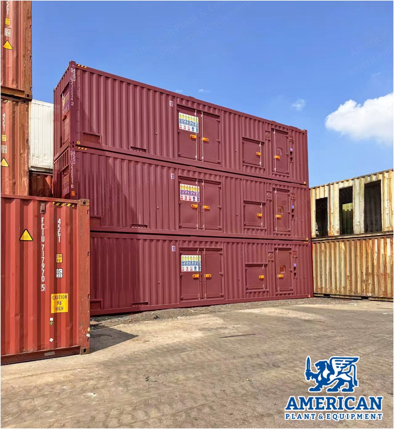
Description Overview MTU 16V4000L64FNER natural gas genset Year: 2022 Hours: zero Containerized type For continuous application 2028 kWe, 400 V, 50 Hz, 1500 rpm, NOx 500 Powered by MTU gas engine 16V4000L64FNER Containerized design with ISO 40 high cube container Cooling system for engine and mixture cooling circuit (heat recovery optional for CHP applications) Generator output field including customer connection MCS (module control system) for containerized system control, regulating, diagnosis and protection Container Features Full transportability of the system (rail, road, sea) Lloyd's CSC-certified (convention safety container) for trouble-free conventional transport (rail, road, sea) and stackable storage of the modules Plug and play solution for ease of on-site installation and operation Versatile use of the gensets (different operating conditions) Weather-proof Minimum external dimensions, ISO 40'HQ container Proven tested design (extensive testing before launch as standard products) Combinable optional packages to suit various demands Environment friendly provision (e.g. low noise level, container floor sealed against leaking oil and water, optional catalytic converter and CHP unit) Acoustic Sound pressure level: 95 dB(A) Tolerance: +2 dB(A) Distance from genset: 1 m Reference height above ground: 1.5 m Optional sound pressure level: 65 / 75 dB(A) Design Conditions Ambient temperature: 0 °C to 40 °C Ambient humidity: 60% Altitude: 100 m Applicable Standards Low voltage directive 2006/95/EG EMV directive 2004/108/EG Lloyd's CSC certified Corners of container (ISO 1161) Protective coating (CSN EN 12944) Safety instruction according to international standard (ISO 3864 / ANSI Z535) Conformité Européenne (2006/42/EC, 2014/35/EU, 97/23/EC) Color Scheme Engine, generator: RAL 7001 Frame: RAL 5002 Control cabinet: RAL 7035 External surface of container (if option selected, customer shall advise color code): RAL 9003 Engine Specifications Engine model: 16V4000L64FNER Number of cylinders / configuration: 16V Engine speed: 1500 r/min Bore: 170 mm Stroke: 210 mm Displacement: 76.3 L Mean piston speed: 10.5 m/s Compression ratio: 12.5 BMEP at nominal engine speed min-1: 21.8 bar Lube oil consumption: 0.35 dm³/h Internal Consumption Internal consumption for the radiator: 10.68 kWe Internal consumption for HT and LT pump: 20.7 kWe Internal consumption of ventilation: 6.2 kWe Fans battery charger: 4 kWe Coolant heater: 9 kWe Anti-condensation heater: 1.2 kWe Engine Coolant Coolant temperature (in/out): 78 / 92 °C Coolant flow rate: 74.7 m³/h Max operation pressure: 6 bar Pressure drop, design: 2.88 / 44.7 bar / m³/h Mixture Cooler 2nd Stage, External Coolant temperature (in/out), design: 58 / 60.2 °C Coolant volumetric flow, design, constant: 34.3 m³/h Pressure drop, design: 0.48 / 50.6 bar / m³/h Max operation pressure before mixture cooler: 6 bar Exhaust Gas Emissions NOx, stated as NO2 (dry, 5% O2): < 500 mg/m³ i.N. CO (dry, 5% O2): < 1000 mg/m³ i.N. HCHO (dry, 5% O2): < 102 mg/m³ i.N. Reference Fuel Natural gas: CH4 > 95 vol% Minimum methane number: 80 MN Range of heating value, design / operation range: 10-10.5 / 8.0-11.0 kWh/m³ i.N. Nominal size / gas pressure min-max: 100 DN / 155-250 mbar Exhaust System Exhaust gas temperature (after turbocharger): 424 °C Exhaust gas volume flow, wet: 8274 m³ i.N. n/h Exhaust gas volume flow, dry: 7409 m³ i.N. n/h Exhaust gas mass flow, wet: 10522 kg/h Exhaust back pressure min-max: 30-60 mbar Liquid Capacity Lube oil for engine: 330 liter Coolant for engine: 270 liter Intercooler coolant capacity: 25 liter Alternator Rating power (temp. rise class F): 2800 kVA Insulation class / temp. rise class: H / F Winding pitch: 2/3 Protection: IP23 Max allowable PF inductive (overexcited) / capacitive (under excited): 0.8 / 1.0 Voltage tolerance / frequency tolerance: ±5 / ±5 Cooling System Rated radiator temperature: 40 °C Antifreeze cooling medium: 35% Standard Features Radiator for engine cooling water circuit and gas mixture cooling circuit Radiator exhaust air via roof Stainless steel piping Temperature control via mixing valve in gas mixture cooling and engine cooling water circuits Integrated control, safety and shut-off devices in the cooling water circuits Closed cooling system Intake and exhaust air with protective grid Intake and exhaust air with sound attenuated louvers Exhaust air at the front part of container Intake and exhaust air with weatherproof grid Conveyance of the required air volume by means of axial fans Optional Items Air intake with sand filter and protective grid Air intake with filter mats Engine cooling water heat recovery Protective Equipment (Standard Features) Fire alarm system (horn light) Gas alarm system (horn + light) Leakage monitor for oil sump Optical alarm for bus bar under voltage Safety instructions according to international standard (ISO 3864 / ANSI Z535) Fire extinguishers (hand held type) at the access doors Emergency-stop button at the access doors (outside) Complete generator output field installed on the container wall Access from outside at one side of the container through lockable access doors Optional Items Work platform Generator Output Field (Standard Features) Isolating switch for power supply of auxiliary drives 3P isolating switch for generator voltage 3P isolating switch for bus bar voltage Connection of customer power cable Lighting Complete lighting consisting of 230 V 50 Hz Emergency lights Lighting for emergency exit in accordance with EU 89/654/EWG Optional Item Option DC 24V lighting Gravity-Operated Lube Oil System (Top Up System), Optional Extra lube oil tank Controlled via MCS Automatic refilling system High/low level monitor Minimum volume monitor for lube oil tank Lubricating oil pump for draining the oil sump (including two solenoid valves) MIP and MCS Gas Genset Control System MTU interface panel (MIP) mounted directly on the base frame of all MTU systems, manages engine and generator operation Controls paralleling and synchronizing with other sources of electricity, such as the utility or other generator sets Provides remote access and software interfacing capabilities Genset control PLC Interface to engine control unit ECU Interface to alternator Bus interface to external (Modbus) On-base components cabled to MIP MCS (module control system) highly customizable solution, links with MIP engine and generator set controls by cable Operator interface DC power supply Data logging capability Remote connection to MTU available Control of off-base components MIP/MCS consolidates generator set controls, starter battery charger, gas train control, and engine oil