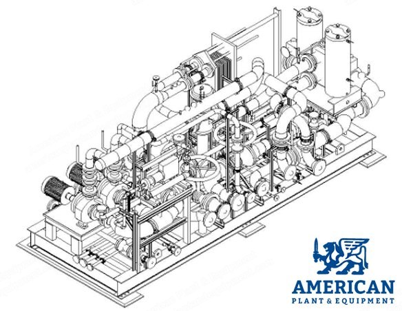
Start air system consists of electric motor driven reciprocating compressors (1 working + 1 standby), air receivers, and control air module.
Compressed air system includes electric motor driven reciprocating compressors (one working and one standby), air filters, and pre-filters.
System designed and regulated to maintain required pressure and demands for engine starting and control, including a minimum of three (3) starts for the engines.
Starting system designed to recharge receiver tank within approximately 60 minutes from minimum recharge pressure to 30 bar pressure.
Start air compressor: 2 working / (1 working + 1 standby).
Compressor capacity: 180 m3/hr FAD each at 1 bar barometric pressure.
Pressure required: 30 bar.
Cut in: 22 bars.
Cut out: 30 bars.
Motor: TEFC motor, 3-phase, 415 V, 50 Hz.
Control panel includes DOL starter of suitable capacity, miniature circuit breaker, auto/manual/selector switch, manual start/stop push button, and suitable control fuses and indications.
DOL starter: 3-phase, 415 V, 50 Hz.
Moisture separator of appropriate capacity with automatic drain trap mounted.
Engine starting air receiver: 1 nos per 2 engines.
Air receiver designed as per European PED and hydro tested at 45 bar pressure.
Receiver mounted with standard fittings and valves.
Receiver fabricated from plate as per P355NL1 / SA 516 grade 60/70.
Air receiver capacity: 2000 litres.
Working pressure: 30 bars.
Design pressure: 33 bar.
Test pressure: 45 bar min.
Number of starts per genset: 3 nos.
Design standard: European PED.
Engine Fuel System
Fuel feeding and boosting system: 2 per plant HFO feeder pump module including feeder pumps (1W+1St.by), filters, PRV, and local alarms.
Feeder pumps capacity of suitable capacity at 5 bar each, screw type electric driven.
2 per plant LFO feeder pump module including feeder pumps (1W+1St.by), filters, PRV, and local alarms.
1 per engine HFO booster module including booster pumps (1W), filters including coarse and fine, de-gasing tank, viscometer, steam heaters, fuel flow meter, local alarms, and fuel change over 3-way solenoid valve.
1 per engine emergency fire control solenoid isolation valve.
1 per plant pressure regulating valve.
Lube Oil System
Lube oil treatment system: 1 per engine lube oil centrifuge with accessories.
Lube oil centrifuge capacity: 2.0 m3/hr.
Centrifuge is solids discharging (self cleaning) total discharge type.
Lubricating oil treatment module receives oil from engine sump, treats to remove solids and water, and returns treated oil to engine sump; designed for continuous automatic operation.
Each centrifuge includes a suction pump complete with strainer to take oil from engine sump and deliver to centrifuge.
Centrifuge is fully automatic with manual stop/start and timed self cleaning operation.
1 per plant hydrophore unit for lube oil centrifuge.
Charge Air System
Air intake filter integrated with baffled type air intake silencer: one set per engine.
Intake air filter installed outside engine hall, draws air from ambient, filters dust particles, and supplies clean air to engine.
Designed for +5 deg C to +35 deg C ambient temperature.
Supply includes set of intake louvers with bird screen, an auto viscous filter (rotating oil bath filter), dry filter, and air intake silencer to meet noise 85 dB(A) at 1 meter from intake air filter.
MS housing with epoxy paint, base frame, stiffeners, instrumentation, control and starter panel, outlet flange with mating flange.
Type: viscous and dry.
Design flow: as per OEM design.
Drive: electric motor (IEC motor).
Filtration efficiency: 95% down to 5 micron particle size.
Motor: 3-phase, 415 V, 50 Hz.
All surfaces adequately protected by suitable paint system including all bolts and fasteners; preparation and materials suitable for environment and max surface temperature as defined.
Plant Water and Engine Cooling Water System
Radiator cooler: 1 set per engine.
Engine cooling system uses suitable sized radiator cooler as per Bergen engines standard scheme.
Radiator dissipates HT and LT water system heat to atmosphere; designed for 35 deg C ambient air inlet temperature.
Ambient temperature design: 35 deg C.
Type: sandwich type air cooled for LT and HT circuit.
Control: EC / (IEC+VFD).
Noise level: 85 +/- 3 dB(A) per radiator under free field condition at a distance of 1 meter.
LT cooling water recirculating pump: 1 working per engine.
LT cooling water recirculates LT water from LT charge air cooler and lube oil PHE to radiator.
LT pump is centrifugal type with flange mounted motor; mounted and supplied on aux module.
Type: centrifugal.
Discharge pressure: 3 bar.
Drive: electric motor.
Motor: 3-phase, 50 Hz, 415 V.
Exhaust Gas System
Exhaust gas silencer: 1 nos per engine.
Exhaust gas silencer, reactive-absorption and industrial type, attenuation 35 dB(A).
Silencer fabricated from SA 516 grade 60/70 with suitable fabricated flange ends to connect to exhaust gas ducting.
Expansion bellows: 1 set per engine.
Material of construction of bellows and sleeves: AISI 321; flanges (according to DIN 2501 ND6): IS 2062 grade 2; end connections: ANSI B16.2, ASA 150.
Auxiliary Module
Auxiliary module: one nos per engine.
All loose supplied equipment (fuel system, lube oil system, jacket water system, LT water system) mounted on a common skid, completely piped, cabled, tested, and painted.
Extent of supply includes all equipment, pipes, pipe fittings, valves, supports, clamps, pipe blinds, gaskets, hardware, companion flanges, cable trays, cable, cable gland lugs, surface preparation and painting, fabrication, testing, cleaning, flushing, preserving, and blanking of pipe module nozzles.
Equipment cables terminated to a junction box mounted on aux module.
Equipment mounted on pipe module: lube oil cooler (plate heat exchanger), lube oil filter, lube oil wax type thermostatic valve, engine jacket pre-heater module, HT PID type thermostatic valve, engine jacket after cooling pump, LTCAC 3-way control valve with actuator and positioner, LT wax type thermostatic valve, cooling water pump (1W+1S) mounted on aux module.
Quantity: 11 units.
Request a Quote
✓
Request sent
Thank you, our team will reply to you shortly.
Direct access to our team
Email American Plant & Equipment
Tell us what you want to buy, source, finance, or sell. A machinery specialist will follow up with you.
✓
Thank you. Your request is with the American Plant and Equipment team.
A machinery specialist will follow up with you.
Machinery updates
Subscribe to our email list
Tell us which industries you follow and we will send you the machines that match.
✓
You are on the list.
We will email you when machines that match your interests come in. Unsubscribe from any message.