Guascor, SFGLD560, Containerized Gas Generator Set, 752 kWe, 1200 RPM, 40ft ISO Container
Scroll to zoom
100%
Description
Operating Conditions
Power output and main performance in accordance with ISO3046 (engine) and ISO8258 (genset).
For ambient temperatures higher than 25 °C (77 °F) and altitudes above 500 m (1640 feet) above sea level, correction factors per document IC-G-B-00-001A apply.
Ambient conditions: extreme tropical conditions.
Maximum temperature: 35 °C / minimum temperature: 15 °C.
Relative humidity: 99%.
Altitude above sea level: 500 m.
Generator Set Performance
Gas genset Guascor SFGLD 560/55 at 1200 RPM.
Rated power output between 610 and 752 kWe depending on methane number (MN) of the gas (MN=45 to MN=75).
Apparent power at generator terminal with leading power factor = 0.8 is between 762 and 937 kVA depending on MN of the gas.
Included Components
Gas engine.
Synchronous alternator.
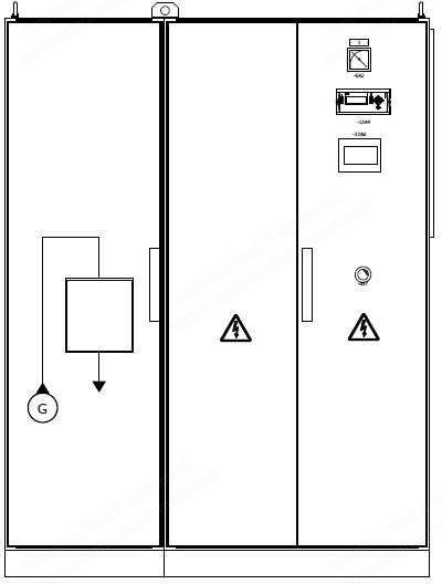
Control and power cabinet.
Starting system.
Air intake system.
Fuel system.
Lubrication system.
Exhaust system.
Engine cooling system.
Enclosure and engine room ventilation system.
Electrical services and miscellaneous elements.
Electrical control and power installation within the container.
Engine Specifications
Model: Guascor SFGLD 560/55 at 1200 heavy duty.
Cycle: Otto, 4-stroke gas.
Intake type: turbocharged and aftercooled.
Maximum mechanical power output (ISO 3046/1): 788 kWm.
Rating: continuous.
Speed: 1200 RPM.
Number of cylinders/configuration: 16 V.
Cubic capacity: 56 liters.
Piston bore: 160 mm.
Piston stroke: 175 mm.
Direction of rotation: counter clockwise viewed from flywheel.
Basic Engine Configuration
Low compression ratio (LCR) pistons.
Forced-lubrication cylinder heads.
Flywheel housing SAE 00.
Flywheel gear.
Rear geared flywheel.
Double vibration shock absorber.
Electronic speed regulator system.
Combustion high efficiency and interchangeable air filters (2).
Circulation of cooling water through 2 centrifugal pumps trailed by gear for high and low temperature water circuits.
Mechanical thermostats (2) for cooling temperature regulation.
Circulation of oil through oil pump bolted to the cylinder block.
Oil refrigeration by heat exchanger cooled-down by low temperature circuit water.
Battery of 3 “full flow” oil filters.
Piston bottom part refrigeration by fixed jets.
Air turbochargers (2).
Turbochargers lube circuits (2).
Charged air intercoolers (2) cooled-down by low temperature circuit water.
Thermal lagging of turbochargers.
24 VDC electric starter.
Intake manifolds (2).
Exhaust manifolds (2) water-cooled by jacket water.
Mechanical control panel including oil pressure and water temperature.
System safety devices (pressure switches, temperature switches, level switches, and engine over-speed protection).
Wiring of all sensors and electrical components of the engine up to a terminal box with emergency stop push button.
Request a Quote
✓
Request sent
Thank you, our team will reply to you shortly.
Direct access to our team
Email American Plant & Equipment
Tell us what you want to buy, source, finance, or sell. A machinery specialist will follow up with you.
✓
Thank you. Your request is with the American Plant and Equipment team.
A machinery specialist will follow up with you.
Machinery updates
Subscribe to our email list
Tell us which industries you follow and we will send you the machines that match.
✓
You are on the list.
We will email you when machines that match your interests come in. Unsubscribe from any message.