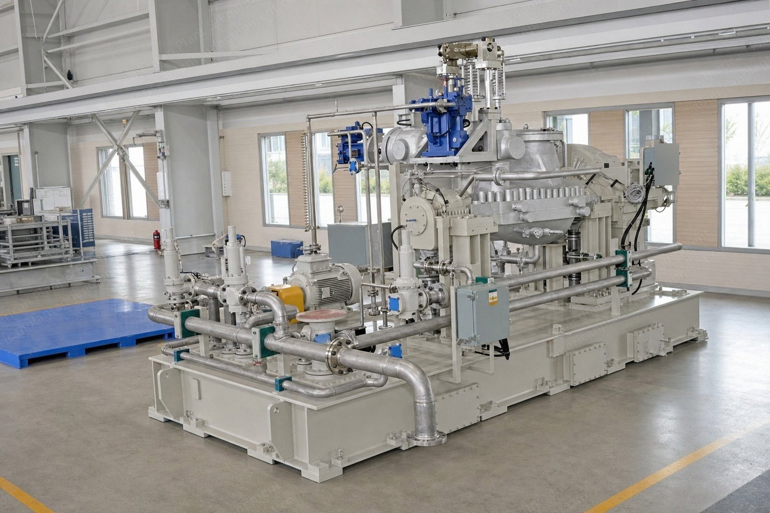
Package comprises a steam turbine, gearbox, lubricating oil system, integrated turbine–gearbox base frame with built-in lube oil tank, AC generator and AVR panel, electrical system, and STG control and supervisory system.
Designed for continuous and reliable operation with minimal maintenance.
Customized design for compact installation with high efficiency.
Rotor machined from a single solidly forged alloy steel block.
Reaction blading with integral shroud.
Horizontal casing split with centerline support.
Labyrinth type steam seals.
Hydraulically operated stop and emergency valve.
Hydraulically operated governing valve.
Motorized barring gear with auto-engagement and auto-disengagement.
Gear Box
Single reduction, double helical gear box with hardened and ground gears.
Reduces turbine speed as per the requirement of the electric generator.
Gearbox output shaft is connected to the electric generator.
Main lube oil pump mounted on the gearbox gear NDE shaft, providing availability of lubricating oil for lubrication and cooling for a significant time even under blackout conditions.
Lubricating Oil System
Steam turbine and gearbox assembly mounted on a single base frame with under-base lubrication oil tank.
All lube oil and control oil pipes, lube oil pumps and other components are mounted within the skid and are factory assembled.
Factory assembly provides precise workmanship with clean aesthetics to the package.
Saves considerable time during erection as there is minimal site work.
Integrated Turbine–Gearbox Base Frame with Built-in Lube Oil Tank
Steam turbine and gearbox are factory-mounted and precisely aligned on a common base frame cum lube oil tank, with the lube oil piping integrated within the skid.
Factory-aligned turbine and gearbox, minimizing site alignment requirements and associated risks.
Integrated lube oil tank and piping, reducing site piping and installation work.
Compact skid design, resulting in reduced equipment footprint.
Reduced erection and commissioning time due to maximum factory pre-assembly.
Reduced site manpower and installation complexity, ensuring faster and more reliable project execution.
AC Generator & AVR Panel
Electric generator is synchronous type rated at 11 KV, 60 Hz, 4 pole design.
CACW cooling arrangement.
AVR comprising auto and manual (1A+1M) mode (ABB make model 1010) used for voltage / PF controlling.
Electrical System
Line side cubicle (LA, SC, PT panel) housing lightning arrester, surge capacitors and potential transformer for generator protection.
Line side cubicle also houses current transformers for input to relays and metering system.
Neutral side cubicle (NGR panel) houses neutral grounding resistor with star point arrangement.
Neutral side cubicle also houses current transformers for input to relays and metering system.
AC motors, S1 duty rating and grade IE2, TEFC, IP55 with DOL starting method.
DC motor, 110 V DC, TEFC, IP 54 protection.
Wall mounted DC starter panel with 2 step resistors start system.
MCC cubicle serves as the auxiliary motor control centre, managing power distribution and control for all auxiliary motors and associated equipment.
STG Control & Supervisory System
STG supervisory panel provides turbine governing, supervisory monitoring and critical protection functions for safe and reliable operation of the steam turbine generator.
Panel incorporates an electronic governor for turbine speed and load control.
Panel incorporates a dedicated overspeed protection system for independent protection against turbine overspeed.
Panel provides necessary indications, alarms, permissive and trip interfaces associated with the turbine.
Panel has suitable communication and hardwired interface provisions with the customer's central control system (PLC/DCS) for coordinated start-up, operation, monitoring, alarm and trip functions.
Controls, sequences, permissives, interlocks and monitoring of STG auxiliary systems are generally implemented in the customer's PLC/DCS.
Sequence descriptions, cause and effect, interlock/permissive logic and relevant I/O/interface details are provided for implementation in the customer's PLC/DCS.
Combined STG Control & Protection Panel
Turbine governor with control and limiter for turbine speed, electrical load and turbine exhaust pressure.
Governor used for turbine speed control from rest to full speed, initiated from the central DCS / PLC system.
Speed governor receives two dedicated turbine shaft speed inputs from speed sensors mounted on the turbine steam end pedestal.
Over-speed protection system for steam turbine tripping in case of over-speed, with 2 out of 3 voted logics.
Over-speed protection system receives turbine speed inputs from 2 dedicated speed sensors mounted on the steam turbine steam end pedestal.
Vibration measurement system comprising vibration probes and transmitter providing input to customer DCS/PLC system for initiation of alarm and trip command in case of excessive vibration.
Generator protection comprising numerical multifunction relay with a MODBUS communication interface with the customer DCS/PLC system.
Metering and synchronization components comprising MFM (multi-function meter), auto synchronizer with synchronization relay and selector switch for manual / auto synchronization.
Supervisory monitoring system comprising BTD and RTDs.
Documentation & Scope Sections
General description, salient features and control philosophy.
Equipment performance.
Utility consumption list.
Scope of supply and equipment features.
Protection and safety system.
Material of construction for major components.
Battery limits of supply.
Exclusions.
Document submission schedule.
Inspection and test plan.
Design basis.
Make of major components.
Request a Quote
✓
Request sent
Thank you, our team will reply to you shortly.
Direct access to our team
Email American Plant & Equipment
Tell us what you want to buy, source, finance, or sell. A machinery specialist will follow up with you.
✓
Thank you. Your request is with the American Plant and Equipment team.
A machinery specialist will follow up with you.
Machinery updates
Subscribe to our email list
Tell us which industries you follow and we will send you the machines that match.
✓
You are on the list.
We will email you when machines that match your interests come in. Unsubscribe from any message.