
Description
Overview
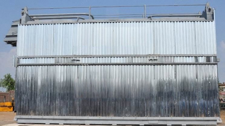
Bi-drum water tube steam boiler, diesel fired, natural circulation, with a convective superheater.
Rated 68,000 kg/hr (68 t/h) of superheated steam, equal to 5,000 BHP.
New, built to order. Quantity 1 machine.
Indoor installation, bottom supported on reinforced concrete construction. Forced draught.
Design ambient 40 C (104 F), relative humidity 60 %.
Steam Output and Pressure
Steam flow at main steam stop valve outlet: 68,000 kg/hr from 105 C (149,914 lb/hr from 221 F) at maximum continuous rating.
Boiler working pressure: 35.15 kg/cm2 (g), that is 500 PSIG (3.45 MPa).
Steam temperature: 400 C (752 F), superheated.
Feed water temperature at deaerator inlet: 80 C (176 F), assumed by the maker.
Deaerator steam requirement: approximately 3,150 kg/hr (6,945 lb/hr).
Superheater
Convective superheater for a steam outlet temperature of 400 C (752 F).
Control range 60 % to 100 % of boiler load.
Mountings: 1 motorised main steam stop valve, 1 pressure gauge, 1 motorised air vent valve, 1 temperature gauge, 1 single post spring loaded safety valve, 1 drain valve.
Fuel and Consumption
Fuel: diesel.
Net calorific value taken: 10,500 kcal/kg (18,900 Btu/lb).
Diesel consumption: 4,680 kg/hr (10,318 lb/hr).
Thermal efficiency: 92 +/- 2 % on NCV, measured to BS 845 Part I indirect method, with radiation loss to the standard ABMA chart.
Burners: 2 x 50 % dual block automatic pressure jet modulating diesel burners with nozzle, ignition transformer, electrodes and flame sensor for auto mode.
Fuel pumping unit, 1 set. Day oil tank 990 litres (262 US gallons) with manhole, inlet, outlet and drain nozzles, level switch and level indicator. Fuel piping from day oil tank to burner on a ring main arrangement.
Heat Recovery, Draught and Fans
Economiser: pressurised, finned tubes with inlet and outlet headers, casing with stiffeners and access doors. Mountings: air vent valve, single post spring loaded safety valve, pressure gauge, drain valve, feed check valve.
Air preheater: reduces flue gas temperature to 160 C (320 F); the recovered heat preheats combustion air.
Draught: forced draught. 2 FD fans with drives, VFD controlled.
Air and gas ducting: flue gas ducting boiler to economiser to air preheater to chimney, and air ducting FD fan to air preheater to burner inlet, with canvas bellows and air damper.
Drums, Water Walls and Pressure Parts
Steam drum: 1, fusion welded with internals, dished ends with steel doors, cross bars, studs and nuts at each end, continuous blow down connection. Seams X-rayed, stress relieved, hydraulically tested, drilled after test.
Steam drum mountings: 1 auxiliary valve, 1 air vent valve, 2 single post spring loaded safety valves, 1 pressure gauge, 2 sets of water level gauges with protectors, 1 blow down valve, 1 feed check valve.
Water drum: 1, at the bottom of the boiler side, fusion welded, same construction and testing, with periodic blow down connection and 1 blow down valve.
Water wall: D type swaged non-membrane construction; front and rear water wall membrane type with headers, risers and downcomers expanded into the drums.
Bank tubes: a set of convection bank tubes expanded between the steam and water drums.
Materials: drum SA 516 Gr. 70; bank tubes and water wall tubes BS 3059 Part II seamless; economiser tubes BS 3059 Part I ERW.
Feed Water, Deaeration and Water Treatment
Boiler feed pumps: 2 multistage centrifugal (1 working + 1 standby) with motors, 75 m3/hr (330 US gpm) at 41 kg/cm2 (583 psi), 2,900 rpm.
Thermal deaerator with head and storage tank: deaeration capacity 74.8 m3/hr (329 US gpm); storage tank sized for 30 minutes hold-up at rated condition; tank steam pressure controlled at 0.3 kg/cm2 (4.3 psi); level controlled by a DP transmitter.
Chemical dosing: LP and HP dosing system with tanks, stirrer, dosing pumps and mountings.
Sample coolers: 3, shell and coil type, for feed water, blow down and steam.
Blow down tank complete with tank, valves and gauges. Automatic timer based blowdown system.
Recommended feed water: TDS 0.1 ppm, total iron below 0.01 ppm, total copper below 0.005 ppm, total silica below 0.001 ppm, oxygen at deaerator outlet below 0.007 ppm, pH 8.5 to 9.5 at 25 C (77 F), hardness nil, CO2 nil, oil and organics nil.
Recommended boiler water: TDS below 200 ppm, hardness nil, residual phosphate 15 to 30 ppm, pH 9.8 to 10.2 at 25 C (77 F), silica below 5 ppm, OH alkalinity 10 to 20 ppm, residual hydrazine 0.05 to 0.1 ppm, amine 2 to 4 ppm.
Controls, Electrics and Instrumentation
Motor supply: 440 +/- 10 % V, 60 +/- 5 % Hz, 3 phase 4 wire.
Instrument and panel supply: 60 Hz, single phase. The supply voltage is to be confirmed by the buyer.
Instrument air: 7.0 kg/cm2 (g) (100 psig), dry and free from oil and dirt, dew point -40 C (-40 F). The air itself is not in the supply.
Control panel: switches, starters, indication lamps, control fuses, main incoming switch and interconnecting wiring, 3B type construction, key lockable. Cubicle in MS CRCA sheet to IP42, coated Siemens grey RAL 7035 or equivalent.
Boiler control and burner management through PLC/DCS, with three element drum level control, O2 trimming and O2 analyser, VFD for the FD fans.
Controls and displays provided: burner management, three element drum level, boiler pressure and combustion, O2 trimming, deaerator level, deaerator temperature and pressure, steam temperature, water flow, fuel flow, air flow, feed water temperature.
Metering: steam and water flow meters (orifice type) and oil flow meter.
Drum water level and temperature control loop: water level controller, water control valve, air pressure regulating valve, air filter, I to P converter, DP transmitter, PID, water temperature and water level indicators. Steam pressure loop: steam control valve, pressure transmitter, PID, air pressure regulating valve, air filter, I to P converter.
Scope of Supply
Main supply: the boiler itself, 2 feed water pumps (1 working + 1 standby), a set of valves and instruments, 2 FD fans with drives, 1 fuel pumping unit, 2 burners.
Heat recovery: 1 economiser, 1 air preheater.
Other accessories: DCS with three element control, VFD for FD fan and O2 analyser; steam, water and oil flow meters; automatic timer based blowdown; deaerator with water storage tank with 30 minutes of storage.
Balance of plant, supplied loose: feed water piping from the deaerator to the feed pump inlet with valve and strainer, up to 30 m (98 ft); feed water piping from the pump to the boiler shell inlet with valve; chemical dosing system.
Fuel handling within scope: day oil tank and fuel piping to the burner ring main.
Vent, drain and safety piping: safety valve exhaust piping to outside the boiler house, blow down piping to the blowdown pit, air vent piping to outside the boiler house, level control and gauge glass drain piping to the blowdown pit, silencers for safety valve and air vent.
Air and gas ducting, insulation on boiler shell, economiser, air preheater, flue gas ducting to air preheater inlet and air ducting from air preheater to burner.
Supporting structure: boiler platform and structure for valve operation, structure for economiser and air preheater, foundation bolts and insert plates.
Electrical cabling and connection from the MCC and PLC control panels to all motors and all supplied instruments.
Battery limits: feed water up to the thermal deaerator inlet; steam at the main steam stop valve outlet; blow down and drains at the blow down header outlet at the pit; exhaust steam and air vent up to safe elevation; cooling and service water and instrument air at individual utility points; fuel at the day oil tank inlet; flue gas at the chimney inlet; electricals at the control panel inlet.
Not Included
All civil and foundation design and works. Foundation load details are provided by the maker.
Pollution and factory approval, and local authority approval at site.
Boiler house and lighting in the boiler house.
Water treatment plant and condensate recovery system.
Main chimney.
Fuel handling system beyond the day oil tank and burner ring main.
Steam piping after the main steam stop valve.
All transportation and transit insurance.
Alkali boil out, first fill lubricants and dosing chemicals.
Erection and commissioning of boiler and accessories.
Utilities: instrument air, water and electricity supply.
Anything not expressly listed in the scope of supply above.
Condition and Supply
Condition: new, built to order.
Quantity: 1 machine.
Delivery: 8 to 10 months from drawing and quality plan approval. Erection, where ordered separately, completed within 12 to 14 months from the same date.
Inspection: to a mutually agreed quality assurance plan, submitted within 1 month of the purchase order. Pressure parts to the applicable boiler regulations with their latest amendments; non pressure parts to the maker's standard engineering practice.
Warranty: 1 year from the date of dispatch against manufacturing defect or faulty workmanship reported in writing within the period. Consequential damages and bought-out items are excluded, and the warranty is void if repairs or replacements are made without written consent.
Makes of bought-out items are indicative and subject to availability at the time of delivery. Figures, specifications, designs and dimensions are subject to reasonable change without notice.