
Description
Overview
Bagasse fired, bi-drum, water tube steam boiler with superheater, reciprocating grate combustion and balanced draft, offered as new manufacture built to order.
Rated output: 94,000 kg/hr (207,000 lb/hr) of superheated steam from 105 C (221 F) feed water, equivalent to 6,000 BHP.
Working pressure: 35.15 kg/cm2 g (500 PSIG).
Steam temperature: 400 C (752 F), superheated.
Thermal efficiency: 68 +/- 2 percent on GCV, BS 845 Part 1 indirect method, with radiation loss to the standard ABMA chart.
Bagasse consumption: 40,850 kg/hr (90,060 lb/hr) at a fuel gross calorific value of 2,250 kcal/kg (4,050 Btu/lb).
Installation: semi-indoor, bottom supported on reinforced concrete construction.
Read the Design Basis And Compliance section below before quoting this boiler. The fuel moisture it is designed on is drier than the fuel specified, and the efficiency and fuel consumption figures above depend on that drier fuel.
This is the larger of two boilers offered together in one package. The other is a 68,000 kg/hr diesel fired bi-drum boiler, our ref V-2396. The two are different machines with different fuels and different capacities; check the ref before quoting either.
Design Basis And Compliance
Bagasse moisture is a genuine mismatch. The boiler is designed on bagasse of moisture less than 45 percent. The specification it was quoted against calls for a maximum bagasse moisture of 48 to 55 percent. This is the single most important open point on this machine.
Both the bagasse consumption of 40,850 kg/hr (90,060 lb/hr) and the efficiency of 68 +/- 2 percent are quoted on that drier fuel. On wetter bagasse the fuel burn rises and the efficiency falls, and neither figure has been restated by the maker for the specified fuel.
Superheat to 400 C (752 F) is offered, but the tolerance is not stated consistently. The covering letter gives 400 +/- 5 C (752 +/- 9 F) and the technical specification gives 400 +/- 10 C (752 +/- 18 F).
Steam temperature departs from design values at low load, below 75 percent of maximum continuous rating.
The 35.15 kg/cm2 g (500 PSIG) figure is stated throughout as a WORKING pressure. No design pressure is stated anywhere in the proposal.
The specification asked for all bagasse feeding infrastructure. The offer includes the rotary drum feeder with pneumatic spreader at the boiler, but fuel storage and the fuel handling system upstream of the feeder are excluded.
The specification asked for the boiler to feed a 7.5 MW back-pressure turbine generator. This proposal covers the boiler island only; no turbine or generator is included in its scope.
The precipitator is not offered complete. Its scope matrix places the casing, the outer and hot roofs, the inlet and outlet cones, the penthouse, the ducting and its supports, and the access platform, staircase and grating on the buyer, while the equipment list separately shows structural and electrical work for the precipitator in the maker supply. The split needs confirming in writing before this boiler is quoted with a complete precipitator.
The proposal states no price, no currency, no price validity and no Incoterm anywhere. It does carry general conditions of sale: an order is accepted only once the agreed advance is realised, and the advance is forfeited if the order is cancelled without the maker written consent.
The maker notes that the technical figures are approximate and that designs, dimensions and descriptions are subject to change without notice.
Steam Generation And Pressure Parts
Two drums, a steam drum and a mud drum, of Class 1 fusion welded construction, 100 percent radiographed, stress relieved and hydraulically tested.
Drum material: SA 515 Gr. 70, with semi-ellipsoidal dished ends, expanded tube end connections, and screen driers plus a mesh pad for steam separation.
Shell and dished ends: ASTM A515 / A516 Gr. 70.
Furnace: membrane water wall, tubes 63.5 mm and 50.8 mm (2.5 in and 2.0 in) outside diameter, tube material BS 3059 Part 2, headers 219 mm (8.625 in) outside diameter in SA 106 Gr. B.
Boiler bank tubes: 50.8 mm (2.0 in) outside diameter, BS 3059 Part 2.
Headers, risers and downcomers: extra thick seamless pipe to ASTM A106.
Primary superheater tubes: SA 213 T11.
Secondary superheater tubes: SA 213 T22.
Superheater headers: SA 335 Part 2.
Painting: red oxide zinc chromate primer.
Combustion, Fuel Feeding And Draft
Combustion system: reciprocating grate with planetary gear mechanism.
Fuel feeding: rotary drum feeder with pneumatic spreader feeding bagasse into the combustor, running at 5 to 20 rpm.
Fuel: bagasse, to be free of stone and impurities. Covered fuel storage is recommended by the maker to keep external moisture out in wet seasons.
Start-up fuel: charcoal and diesel.
Draft system: balanced draft.
Forced draft fan: 1 off, centrifugal direct drive, IE-III motor with variable frequency drive, dynamically balanced impeller.
Induced draft fan: 1 off, centrifugal V-belt drive, IE-III motor with variable frequency drive, dynamically balanced impeller.
Secondary air fan: 1 off, centrifugal direct drive.
Gas path: combustion completes over the reciprocating grate and is released into the free board zone; water walls absorb heat before the gases pass to the economiser, air preheater, electrostatic precipitator, induced draft fan and chimney.
Furnace approach: cast iron fire doors and ash doors.
Heat Recovery And Soot Blowing
Economiser: downstream of the boiler bank, in-line plain tubular arrangement, tubes 38.1 mm (1.5 in) outside diameter to BS 3059 Part 2, headers 219 mm (8.625 in) outside diameter in SA 106 Gr. B or equivalent, mild steel casing.
Air preheater: multi-tubular heat recovery unit after the economiser, cross flow, tubes staggered, 60.3 mm (2.375 in) outside diameter, flue gas inside the tubes and air outside, one air and gas pass, mild steel casing.
Soot blowing: retractable soot blowers on the superheater zone; manual soot blowers on the boiler bank and the economiser.
Feed Water And Deaeration
Feed pumps: 2 off, 1 working and 1 standby, KSB centrifugal horizontal multistage hot water design, electrically driven, on base frames with motors.
Feed pump duty: 105 m3/hr (462 US gpm) at 420 m (1,378 ft) head.
Deaerator with storage tank, capacity stated as 103,400 m3/hr, storage sized for 30 minutes at 30 m3 (7,925 US gal), to be placed on a civil structure.
Deaerator steam requirement: approximately 4,400 kg/hr (9,700 lb/hr).
Feed water temperature: 105 C (221 F) to the boiler, 80 C (176 F) assumed at the deaerator inlet.
Automatic water level control: three element controller with control valve, high and low level annunciation with audible alarm and visual indication, and a lockout with alarm on extreme low water.
Chemical dosing: low pressure and high pressure dosing systems included in the balance of plant supply.
Recommended feed water quality: TDS 0.1 ppm, total iron below 0.01 ppm, total copper below 0.005 ppm, total silica below 0.001 ppm, oxygen at deaerator outlet below 0.007 ppm, pH at 25 C of 8.5 to 9.5, total hardness nil, total carbon dioxide nil, oil and organics nil.
Recommended boiler water quality: TDS below 50 ppm, total hardness nil, residual phosphate 15 to 30 ppm, pH at 25 C of 9.8 to 10.2, silica below 5 ppm, hydroxide alkalinity 10 to 20 ppm, residual hydrazine below 0.05 to 0.1 ppm, amine 2 to 4 ppm.
Mountings And Fittings
On the steam drum: 1 air vent valve, 2 single post spring loaded safety valves, 2 sets of reflex water level gauges, 1 pressure gauge, 1 blowdown valve, 1 check valve and 1 continuous blowdown valve for TDS control, plus a periodic blowdown connection with internal pipe.
On the superheater: 1 motorised main steam stop valve, 1 pressure gauge, 1 motorised air vent valve, 1 temperature gauge, 1 single post spring loaded safety valve and 1 drain valve.
On the economiser: 1 air vent valve, 1 pressure gauge, 1 drain valve and 1 feed check valve.
On the water wall headers: 4 drain valves.
Controls And Electrics
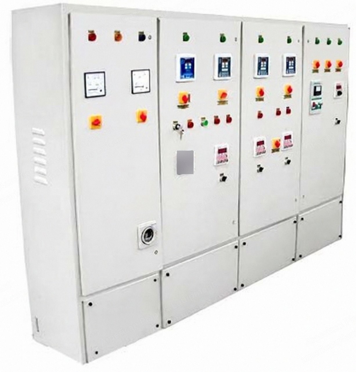
DCS cum control panel with three element control system, furnace draft control, and variable frequency drives on the forced draft fan, induced draft fan, fuel feeder and feed pump.
Instrumentation includes orifice type steam flow and water flow meters and temperature indicators with selector switch.
Interlocks: the forced draft fan cannot run unless the induced draft fan is running, the fuel feeders cannot run unless the forced draft fans are running, and a safety device trips the boiler on low water level.
Annunciation for forced draft fan trip, induced draft fan trip, feed pump trip and low drum level.
The boiler can run in automatic or manual mode and can be set to start and stop automatically within a pressure band of 3 to 5 kg/cm2 (43 to 71 PSI).
Motor control centre: fixed non-draw-out modular type, single front, indoor, bottom cable entry, with switches, motor starters, indication lamps, control fuses, main incoming switch and interconnecting wiring for the forced draft fan, induced draft fan and both feed pumps. The panel is key lockable.
Motor supply: 440 +/- 10 V, 60 +/- 5 Hz, 3 phase 4 wire.
Instrument and panel supply: single phase, 60 Hz; the voltage is left open in the proposal for the client to confirm.
Cooling water requirement: 6 m3/hr (26.4 US gpm).
Instrument air: 7.0 kg/cm2 g (100 PSIG), dry and free from oil and dirt, dew point -40 C (-40 F).
Site design conditions: ambient 40 C (104 F), relative humidity 60 percent.
Ash Handling And Emissions Control
Furnace ash: submerged wet ash handling system with a belt conveyor of approximately 10 m (33 ft). Ash disposal at the conveyor outlet is not included.
Fly ash: dense phase pneumatic ash handling system collecting from the air preheater and the electrostatic precipitator, with a 24 hour ash storage silo mounted on civil works.
Rotary air valves at the economiser, air preheater and electrostatic precipitator.
Electrostatic precipitator: 5 field. The maker supplies the precipitator internals, gas distribution devices, C-profile collecting electrodes, spike-on-pipe discharge electrodes, tumbling hammer rapping gear, support insulators, insulator heaters with thermostat, hopper heaters, slide support bearings, manual high tension grounding switches and the doors, together with the structural and electrical work and the insulation for the precipitator.
Precipitator items the scope matrix places on the buyer rather than the maker: the casing, the outer roof and the hot roof, the inlet and outlet cones, the penthouse, the ducting and its supports, and the access platform, staircase and grating.
Electrostatic precipitator outlet emission level: 150 mg/Nm3.
Electrostatic precipitator controls: transformer rectifier sets with mineral oil, control panel and controllers, mechanical key safety interlock system, and a non-draw-out motor control centre with power feeders for the transformer rectifier sets and rapping motors.
Electrostatic precipitator battery limits: flange at the inlet cone, flange at the outlet cone, and the outlet flange of the hopper.
Balance Of Plant Included
Feed water piping from the feed water tank to the deaerator to the feed pump inlet with valves and strainer, maximum 25 m (82 ft).
Feed water piping from the feed pump to the economiser inlet and boiler shell with valves.
Safety valve exhaust piping to the outside of the boiler house, with silencers for the safety valves.
Blowdown piping to the blowdown tank, maximum 25 m (82 ft); air vent piping to the outside of the boiler house; level device and gauge glass drain piping to the blowdown tank; instrument piping within the boiler house.
Flue gas ducting from the boiler to the air preheater, air preheater to the electrostatic precipitator, precipitator to the induced draft fan and induced draft fan to the chimney tie point; air ducting from the forced draft fan to the air preheater and on to the boiler wind box; expansion bellows and dampers for air and flue gas.
Refractories for the furnace: fire bricks, fire crete, fire clay, castable, mill board and red bricks to the maker standard layout.
Insulation on the furnace water walls, boiler bank, steam and water drums, air preheater, flue gas ducting up to the induced draft fan, and the electrostatic precipitator.
Supporting structure for the boiler platform and for the air preheater.
Electrical cabling and connection from the control panels to all motors and supplied instruments.
A set of tentative general arrangement and foundation drawings for guidance, with a complete certified drawing and document set issued 4 to 6 weeks after dispatch of the boiler.
Battery Limits
Steam: outlet of the main steam stop valve.
Feed water: inlet of the deaerator cum water storage tank.
Blowdown and drain: outlet of the blowdown tank.
Flue gas: inlet of the chimney tie point.
Fuel: inlet of the rotary drum feeder.
Ash: outlet of the economiser, air preheater, electrostatic precipitator and slide gates on the boiler, or the outlet of the ash silo for fly ash and the outlet of the belt conveyor for wet ash.
Electricals: inlet of the DCS cum control panel.
Exclusions
Water treatment system and condensate recovery system.
Main chimney.
Fuel storage and fuel handling system.
Ash disposal system beyond the stated battery limits, and dust disposal beyond the precipitator hopper discharge flange.
All civil design and civil work for the boiler and for the precipitator and its control room, including the earthing pit and blowdown pit.
Erection and commissioning of the boiler, its accessories and the electrostatic precipitator.
Labour, tools, tackles, utilities and consumables for assembly, erection and commissioning, including charcoal, lignite, kerosene, inert materials, cleaning and lubricating agents.
Local site welding of riser and downcomer pipes and its approval.
All transportation and transit insurance.
Pollution and factory approvals, performance testing and third party inspection.
Boiler house and lighting in the boiler house; area and equipment illumination, lightning protection and distribution boards; complete equipment earthing and earth pit; finish painting.
All steam piping, valves, pressure reducing station and header required after the main steam stop valve.
All utilities: air, water, electricity and chemicals.
Monorail structure with manual hoist; air conditioning and ventilation for the control room.
Any item or service not specifically listed in the scope of supply.
Condition And Supply
Condition: new, manufactured to order against this specification.
Quantity: 1 boiler.
Delivery: 10 to 12 months from the date of a technically and commercially clear order accompanied by the necessary advance. Equipment is dispatched in lots.
Warranty: 12 months from the date of dispatch against manufacturing defect or faulty workmanship reported in writing within the warranty period. Bought-out items and consequential damages or losses are excluded, and the warranty is void if repairs or replacements are made without the maker written consent.
Pressure parts are built to the governing national boiler regulations with their latest amendments; non pressure parts to the maker standard engineering practice.
Structural design allowances for wind load and seismic coefficient follow the applicable national standards.
No price, currency, price validity or Incoterm is stated in this proposal. The only payment condition given is that an order is accepted once the agreed advance is realised.