
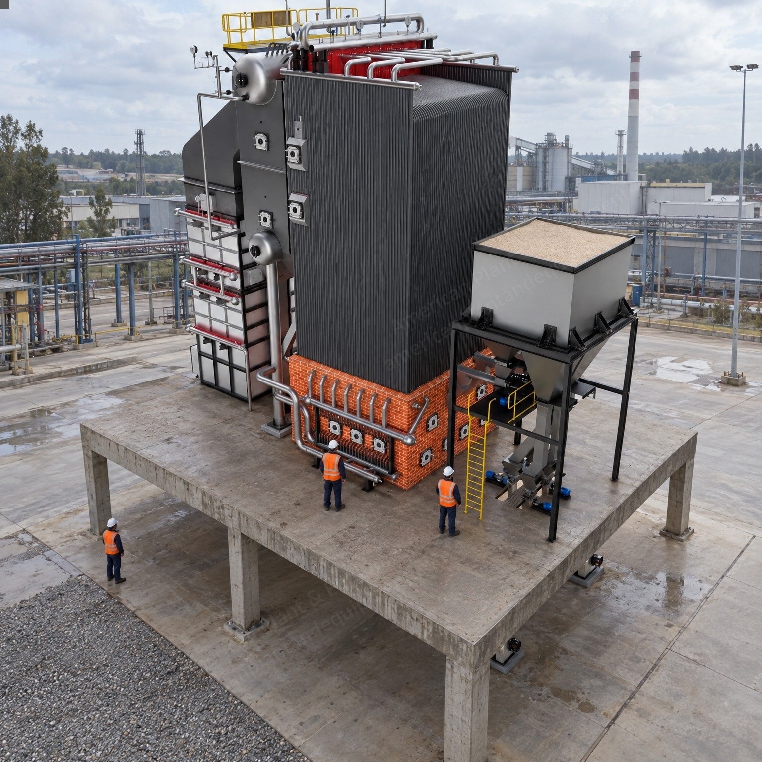
Description
Overview
Complete steam and power package: one bagasse fired, bi-drum, natural circulation water tube boiler with superheater and reciprocating (Resi) grate, and one 12 MW back pressure steam turbine generator (STG) set with auxiliaries.
New manufacture, designed, built and supplied to order.
Boiler maximum continuous rating (MCR): 90 TPH, 90,000 kg/hr (198,416 lb/hr) of superheated steam; peak generation 110% of MCR for half an hour in 8 hours.
Steam at the superheater / main stop valve outlet: 47 kg/cm2 (g) (668 psig) and 480 +/- 5 C (896 +/- 9 F) guaranteed.
Turbine: 12.0 MW, power output 12000 kW, through a gearbox to a 15000 kVA, 11 kV, 50 Hz alternator; inlet 90 TPH at 45 kg/cm2 g (640 psig) and 480 C (896 F); back pressure exhaust 90 TPH at 2.0 kg/cm2 g (28 psig) to process.
Main fuel: 100% bagasse with 50% moisture; start-up fuel: wood mixed with diesel; bagasse consumption 39550 kg/hr (87,193 lb/hr) approx.
Boiler efficiency: 71 +/- 1% at 100% bagasse, ASME PTC 4.1 indirect abbreviated heat loss method on GCV basis.
Number of boilers: 1 (One). Number of steam turbine generator sets: 1 (One).
Design Data
The following parameters are the basis for the design of the boiler.
Combustion system: Resi grate combustion. Draft system: balanced draft.
Maximum continuous rating (MCR): 90 TPH. Peak load for half an hour in 8 hours: 110% of MCR.
Steam pressure at the stop valve outlet: 47 kg/cm2 (g). Steam temperature at the stop valve outlet: 480 +/- 10 C design range (480 +/- 5 C guaranteed).
Feed water temperature at the deaerator outlet: 105 C (221 F). Flue gas temperature at the air preheater (APH) outlet: 140-150 C (284-302 F).
Superheater temperature control range: 60 to 100%. Minimum continuous rating with auto: 60%.
Mean ambient air temperature: 35 C (95 F). Relative humidity: 70%.
Fuel: main fuel for MCR generation 100% bagasse; start-up fuel wood mixed with diesel; fuel sizing 100% below 25 mm (1 in).
Boiler efficiency (ASME PTC 4.1) at 100% bagasse: 71 +/- 1%.
Boiler construction: natural circulation bi-drum; top supported; membrane panel furnace; design code: the statutory boiler regulations with latest amendments.
Feed water analysis (to be maintained by the Purchaser): general appearance clear and colorless; total hardness as CaCO3 0 ppm; pH at 25 C 8.5-9.5; dissolved oxygen 0.007 ppm max; iron 0.01 ppm max; copper 0.005 ppm max; silica below 0.02 ppm; conductivity at 25 C (uS/cm) nil; hydrazine residual nil.
Boiler water analysis (to be maintained by the Purchaser): general appearance clear and colorless; total hardness as CaCO3 0 ppm; pH at 25 C 10.8-11.2; silica 5.3 ppm max; total dissolved solids 200 ppm max; conductivity at 25 C (uS/cm) nil; hydrazine residual 0.02 ppm max; phosphate residual 20-40 ppm.
Blowdown: continuous 3.0% (approx.); intermittent 5.0% (approx.).
Electrical power for LT motors: 415 V +/- 10% AC, 50 Hz +/- 5%, combined variation on voltage and frequency 10%, AC 3 phase 4 wire.
Electrical power for instrumentation: field switches, level gauge illumination, solenoid valves, etc. 230 V AC single phase, 50 Hz; field transmitters 24 V DC.
Chemicals for dosing: HP dosing tri-sodium phosphate; LP dosing hydrazine.
Cooling water: inlet 32 C (ambient at the battery limit); outlet 8 C rise; pressure 3-4 kg/cm2 g at the battery limit; clear and colorless; quantity to be advised later.
Instrument air: 4-5 kg/cm2 g, ambient temperature, oil and moisture free, dew point -40 C; quantity to be advised later.
Plant air: 4-5 kg/cm2 g, ambient temperature, oil and moisture free; quantity to be advised later.
Site conditions: site location, seismic design, design wind velocity (m/s) and height above mean sea level (m) to be confirmed for the site; ambient temperature for electrical motors 45 C (113 F); ambient temperature for boiler design 35 C (95 F); relative humidity 70%; area classification safe and non-hazardous; environment non corrosive; boiler location outdoor installation.
Number of boilers: one.
Major design codes: pressure parts to the statutory boiler regulations with latest amendments; piping ASME B 31.1; non-pressure parts as per standard engineering; fans as per vendor; process valves ASME B16.34; boiler performance testing ASME PTC 4.0; radiation loss as per ABMA chart.
Design fuel ultimate analysis, bagasse, % by weight: carbon 23.50, hydrogen 03.25, nitrogen 00.00, sulfur 00.00, moisture 50.00, ash 3.0, oxygen 20.25, total 100; GCV 2272 kcal/kg.
Boiler Description
The boiler consists of a Resi grate combustor, membrane panel, superheater, bi-drum, bank tubes, economizer, air preheater and boiler auxiliaries. Fuel is fed into the combustor through fuel feeders; the flue gases leaving the combustor flow into the boiler section, where they are cooled while generating superheated steam from the feed water entering the bank tubes, and the cooled flue gases leave to atmosphere through the stack.
Salient features: fully welded construction; bi-drum type; membrane panel furnace; Resi grate for automatic ash discharge; ESP for pollution control.
General design: natural circulation boiler with all pressure parts of welded construction; tube diameter and spacing specifically designed for optimum heat transfer and fluid velocity; designed to the statutory boiler regulations; the membrane forms a gas tight casing on the outside surface; internal insulation keeps the outer casing cool; the steel frame is located outside to reduce thermal effects on the structural members.
Boiler drums: minimum one steam drum and one water drum, both of fusion welded construction, with dished ends, manholes and doors fitted with crossbars, studs and nuts at each end. The steam drum has primary and secondary separators to promote circulation and ensure high steam purity, and connections for the feed water line, chemical dosing, continuous blowdown, direct water level gauge and safety valves. The water drum has connections for intermittent blowdown and downcomers.
Membrane panel furnace: designed for maximum continuous rating on 100% bagasse firing, with the fuel fired on the Resi grate fitted in the furnace and a combustion chamber with all accessories. Water cooled side, front, rear and roof wall tubes, suitably manipulated to provide access, inspection and peep doors and spouts. Ash hoppers below the furnace chamber; the furnace is placed at an elevated height from the ground; operating platform in MS and +300 mm columns in RCC.
Headers: boiler headers for the furnace wall tubes, with stubs and drain connections.
Superheater: primary and secondary superheaters, superheating the total steam generated to a final temperature of 480 +/- 5 C at 60 to 100% MCR, complete with interconnecting pipelines and mountings (safety valves, drain / air vent valves, pressure gauges). Manifolds fabricated from solid drawn seamless pipes with air vent branches; a thermowell in the secondary superheater outlet manifold measures the superheated steam temperature.
Attemperator: spray type (or heat exchanger type) between the primary and secondary superheaters, holding the superheater outlet steam temperature at 480 +/- 10 C at steam flows between 60 and 100% of MCR.
Convection bank / boiler bank: bank tubes expanded into the steam drum and water drum for natural circulation; half of the bank tubes work as downcomers and half as risers; the convection bank is the major convective heat transfer area of the boiler.
Economizer: plain tube type in the second pass, between the boiler bank and the air preheater, complete with inlet and outlet headers, coils, coil supports, thermowells for inlet and outlet water temperature, casing, ducting and lagging; the feed water temperature rise stays below the saturation temperature.
Air preheater: tubular air heater with ERW tubes, tube sheets, supports, dampers, casing and ducting; cold air entry distributed over the length of the air heater; the air heater and economizer are designed for a final flue gas temperature of about 150 C.
Fuel firing equipment: front discharge type Resi grate; pneumatic spreaders mounted on the boiler front spread the fuel uniformly over the grate for complete combustion and improved efficiency; pulsating dampers at the spreader air entry; high pressure air from the secondary air fan distributes the fuel.
Induced draft (ID) fans: 2 x 60%, simply supported, designed for a discharge capacity at least 25% above the theoretical flue gas quantity and a head 30% above that required at rated MCR; renewable hard faced wear pads on the impeller blades; complete with impeller, shaft, bearings, casing and damper; speed below 980 rpm; electric motor with VFD drive.
Forced draft (FD) fans: 2 x 60%, simply supported, designed for a discharge capacity at least 15% above the theoretical air quantity and a head 20% above that required at rated MCR; air supplied underneath the furnace; complete with impeller, shaft, bearings, casing and suction damper; rated speed below 1440 rpm; electric motor with VFD.
Secondary air (SA) fans: 2 x 60%, simply supported, supplying high pressure secondary air into the furnace through heat resisting nozzles installed in the furnace walls for complete combustion; isolating / controlling dampers at the fan suction and in the duct; directly coupled to the motor; speed below 1440 rpm; VFD.
Feed water pumps: 3 x 60% (2 working + 1 standby), including margins on MCR, multistage, each suitable for hot water at 105 C from the deaerator to the boiler, each driven by a TEFC squirrel cage motor with VFD.
Soot blowing: steam operated motorized soot blowers at the boiler bank, economizer and air preheater, plus motorized automatic retractable soot blowers for the superheater.
Blowdown: continuous blowdown arrangement with a common blowdown tank for CBD and IBD; other drains from the water drum and furnace headers are collected in a drain collecting header and discharged to the blowdown tank.
Silencers: two (2) for the superheated steam safety valves; one (1) for the start-up vent.
Deaerator with deaerated water tank: deaerator mounted on a deaerated water tank of 20 minutes storage, suitable for a maximum flow of 108 m3/hr, raising the feed water to 105 C with exhaust steam at 1 kg/cm2 as bleed or from the turbine exhaust; mounted on top of the RCC control room; high and low level alarms with gauge glass.
HP and LP dosing: one high pressure and one low pressure chemical dosing system, each with chemical proportioning tanks, two positive displacement dosing pumps (one standby), valves and measuring instruments; each mixing tank with motorized stirrer, piping and fittings; tank capacity 400 liters each; located near the feed water station on the ground floor.
Feed water valves: 3 motorized isolation valves at the boiler feed pump discharge; 2 x 100% feed water control valves with manual isolation valves upstream and downstream of each; 1 x 30% feed water control valve with manual isolation valves; one NRV in the feed water line before the economizer; one manually operated isolation valve at the economizer inlet.
Spray and steam valves: 1 pneumatically operated spray control valve with manual isolation valves upstream and downstream and 1 manual bypass valve; main steam stop valve, motorized, with motorized external bypass; start-up air vent valve, pneumatic, with manual isolation valve; 1 NRV in the main steam line; 1 motorized valve for steam inlet to the soot blower PCV; one motorized valve each for IBD and CBD; 1 motorized isolation valve for steam inlet to the turbine.
Safety valves: spring loaded mechanical safety valve on the main steam line; spring loaded mechanical safety valves on the drum, 2, and at the superheater outlet, 1.
Other valves: all statutory code valves in the steam line, feed line (feed pump delivery valves motorized) and spray line; required isolation, drain and root valves.
Instrumentation and control: DCS based, monitoring the control loops and parameters such as pressure, temperature and draft; steam flow meter and feed water flow meter (integrating, indicating in the data logger); drum water level and superheated steam pressure indicated in the data logger.
Multipoint temperature scanner with K/J type thermocouples and universal temperature transmitters with linear output, all recorded in the data logger, at: final and primary superheater outlet steam; economizer inlet and outlet feed water; deaerator inlet feed water; flue gas at the boiler outlet, economizer outlet, air heater outlet and ID fan inlet; air at the air heater inlet and outlet; furnace.
Draft gauges at: FD fan discharge; ID fan suction; furnace; flue gas at the boiler outlet, economizer outlet, air heater outlet and ESP outlet; air at the air heater outlet.
Pressure gauges: 250 mm diameter with siphon and isolation valve at the boiler drum, the superheater outlet steam and at fire door level for superheater outlet steam; 150 mm diameter with stainless steel siphon and isolation valve at the economizer inlet and outlet, each feed water pump outlet and the feed water pump common header.
Steam drum gauges: two bicolor multiport water level gauges; pressure gauge and remote pressure gauge.
Automatic controls: three element drum level control (the feed water control valve opens fully if the level falls below minimum and closes fully if it rises above maximum); cascaded superheater steam temperature (attemperator) control measuring at the primary superheater outlet header and the final superheater inlet header; furnace draft control by ID fan speed at -5 to -10 mm WC; deaerator pressure control (regulating steam to hold the feed water temperature) and level control (balancing inflow and outflow). The instrumentation system is placed in an air conditioned room.
Electrostatic precipitator (ESP): three field, complete with TR sets, emitting and collecting system, rapping mechanism and electrical controls; casing, structure and insulation by the Purchaser to the manufacturer's drawing.
Bottom ash: bottom / grate ash falls into the water trough of the submerged chain conveyor (SCC), where it is quenched and cooled to a handling temperature; make-up water piping maintains the water level; the SCC conveys and dewaters the ash before discharge at the designated collection / disposal point.
Fly ash: collected from the economizer, air heater and ESP hoppers and discharged through rotary airlock valves (RAVs), which give controlled discharge and air sealing, into an enclosed pneumatic system to a common fly ash silo; the complete ash handling system is operated and monitored from the central PLC / DCS with interlocks and alarms.
Motor control center (MCC): 14 / 16 SWG CRCA sheet steel, floor mounted, dust and vermin proof, IP52, non-extendable, compartmentalized, bottom cable entry, front operated non-draw out, rubber gaskets on all covers and doors, lifting hooks.
Bagasse handling system: Purchaser's scope.
Doors and peepholes: suitably designed, in suitable numbers.
Painting and finishing: steam drum, water drum, furnace panels, headers and coils painted for protection; final painting at site excluded.
This is the overall system description; it may vary without affecting the performance of the boiler.
Boiler Technical Data
General: bi-drum, water tube, bagasse fired boiler; natural circulation; top supported; 1 (One) boiler; outdoor installation; design code: the statutory boiler regulations with latest amendments.
Predicted performance: MCR 90 TPH; peak generation for half an hour in 8 hours 110% of MCR; steam pressure at the superheater outlet at MCR 47 kg/cm2 (g); steam temperature at the superheater outlet at MCR 480 +/- 5 C; feed water temperature at the deaerator outlet 105 C; flue gas temperature at the APH outlet 140-150 C; ambient 35 C; superheater steam temperature control range 60-100%; minimum continuous rating with auto 60% MCR; excess air 30% max of theoretical air.
Fuel: main 100% bagasse with 50% moisture; auxiliary / start-up fuel wood mixed with diesel; efficiency (ASME PTC 4.1) 71 +/- 1%; bagasse consumption 39550 kg/hr.
Electric supply: supply voltage 415 V +/- 10%; control voltage 230 V DC +10% to -30% for critical auxiliaries and MCC.
Heating surfaces: furnace 632 m2 (E.P.R.S.); boiler bank 819 m2; economizer 2386 m2; superheater 890 m2 (primary and secondary); total 4727 m2; air preheater 3781 m2 or as required.
Temperature profile, gas side: flue gas leaving the furnace (FEGT) 890-910 C; superheater inlet 890-910 C; superheater outlet 550-570 C; boiler bank outlet 330-360 C; economizer outlet 220-230 C; APH outlet 140-150 C. Air side: air preheater outlet 170-180 C. Water side: deaerator outlet 105-110 C; economizer outlet 220-230 C.
Steam drum: inside diameter 1340 mm; overall length 8000 mm; shell / dished end material SA 515 Gr.70 / SA 516 Gr.70; shell and dished end thickness on final design to the statutory boiler regulations; saddle support; 2 spring loaded full lift safety valves on the drum.
Water drum: inside diameter 1000 mm; overall length 8000 mm; shell / dished end material SA 515 Gr.70 / SA 516 Gr.70; shell thickness 56 mm and dished end thickness 45 mm (or as per the statutory boiler regulations); saddle support; internals baffle and demister pad.
Water wall: fin welded membrane wall; tubes 63.5 x 4.06 mm (OD x thickness), SA 210 Gr. A1 or equivalent; headers SA 106 Gr. B or equivalent; fins structural steel, 6 mm.
Superheater: primary (counter flow) and secondary (parallel flow), inline arrangement, both in the convection zone; tubes 38.1 - 50.8 x 4.06 mm; primary tubes SA 210 Gr. A1 / SA 213 T11, secondary tubes SA 213 T11 / SA 213 T22; primary inlet header SA 106 Gr. B, primary outlet header SA 106 Gr. B / SA 335 P11; secondary inlet header SA 106 Gr. B / SA 335 P11, secondary outlet header SA 335 P11 / SA 335 P22.
Attemperator: fixed spray type, 1 (One), between the primary and secondary superheater stages; pipe SA 106 Gr. B / SA 335 P11.
Boiler bank: inline; tubes 50.8 x 4.06 mm (OD x thickness), BS 3059.
Economizer: plain tube, drainable; in-line (horizontal); counter flow; tubes 38.1-50.8 x 3.66-4.06 mm, SA 210 Gr. A1; headers SA 106 Gr. B; casing structural steel, 6 mm.
Air heater: staggered / recuperative; tubes 63.5 x 2.34 mm (OD x thickness), BS 6323 Part V ERW, with the last six rows in Corten steel tube; flue gas inside the tubes, air outside; 2 (Two) blocks.
Soot blowing equipment: long retractable / rotary soot blowers at the superheater zone, boiler bank and economizer; intermittent operation.
Firing equipment: Resi grate, grate area on final design; rotary feeders, quantity on final design; pneumatic spreaders, quantity on final design.
Blowdown tank: 1 common blowdown tank, steel plate, cylindrical.
Sample coolers: shell and coil type, for feed water, drum water and superheated steam; carbon steel shell, stainless steel coil.
Boiler feed pumps: 3 x 60% (2W + 1S), centrifugal; feed water temperature 105; rated flow 67.29; differential head at rated condition 710; motor rating 200 (may change to the vendor's standard); speed 2980; motor voltage 415 V; VFD drive.
Safety valves: steam drum 2; superheater 1; spring loaded.
Fans (FD / ID / SA): quantity 2 x 60% / 2 x 60% / 2 x 60%; capacity 17.63 / 61.24 / 11.76; head 220 / 250 / 670; temperature 40 / 160 / 40; medium ambient air / flue gas / air; speed 1440 / 980 / 1440; motor rating 55 / 220 / 110 (may change to the vendor's standard); VFD on all three; direct coupled.
Deaerator cum storage tank: spray cum tray type deaerator; deaeration capacity 99000; feed water temperature at the deaerator outlet 105; storage tank capacity 20 min (36 m3); saddle support; located above the TG building; shell, dished end and storage tank plate SA 516 Gr.70 / SA 515 Gr.70; spray nozzles and trays SS 304.
Feed water storage tank: vertical, cylindrical, closed top with vent; mild steel (MS), welded construction; 1 (One); capacity to suit; 2 pumps (1W + 1SB), centrifugal.
Chemical dosing (HP / LP): cylindrical tanks, capacity 400 / 400, structural steel; motorized stirrers; reciprocating / diaphragm type pumps; 2 pumps each (1W + 1SB); pump capacity 0-10 / 0-10; motor rating 0.37 / 0.37; chemical dosed tri-sodium phosphate / di-sodium phosphate or hydrazine.
Pollution control: electrostatic precipitator, 3 field; flue gas volume 250,000; dust load at the ESP inlet 5; outlet dust concentration (SPM emission) 75 mg/Nm3 or less.
Boiler Electrical
Boiler section electrical scope, from the MCC to all motors, for the 90 TPH boiler: MCC for the boiler; MOV MCC; soot blower; ash handling system (AHS); MLDB; pump utility MCC; push buttons; supervision of commissioning of the boiler (charged extra); VFDs for the boiler; motors for the boiler.
The above specifications are tentative and may change during final design without affecting the performance of the equipment.
Performance Parameters
At 100% bagasse: steam flow at the main stop valve outlet (MCR) 90 TPH; steam pressure at the main steam valve outlet 47 kg/cm2 (g); steam temperature at the main steam stop valve outlet 480 +/- 5 C; boiler efficiency at 100% MCR output 71 +/- 1% (ASME PTC 4.1 indirect abbreviated heat loss method, GCV basis); fuel consumption 39550 kg/hr (approx.).
The guarantees are based on the performance fuel ultimate analysis given in the design data. The performance test is to ASME PTC 4.1, indirect abbreviated heat loss method on GCV basis, with the ASME suggested tolerance for instrument measurement error.
Conditions of the performance trial: conducted to ASME PTC 4.0 indirect heat loss method on GCV basis; blowdown kept closed; the boiler assembled, commissioned and run under the direction of the manufacturer's staff and to their recommendation; steady state, constant load operation; fuel of consistent composition in heat value and analysis; drum water quality maintained as in the basis of design; any special instruments arranged by the Purchaser / Owner; efficiency subject to the tolerance of measuring instruments per the relevant codes; performance fuel as per the furnished analysis.
Scope Of Supply (Boiler)
Columns of the scope matrix: engineering and drawings / manufacturing and supply / erection and commissioning (E and C); 'Included' means in this supply. Erection and commissioning of every boiler item is by the Purchaser.
Initial activities: GA drawing, included (engineering only); civil loading drawing, included (engineering only); civil foundation drawing, Purchaser / Purchaser / Purchaser; foundation bolts, Included / Purchaser / Purchaser.
Boiler pressure parts, Included / Included / Purchaser: steam drum; water drum; furnace membrane wall panel; boiler bank tubes; downcomers, supply pipes and risers; superheater coils with supports and headers; intermediate attemperator; economizer coil with supports and headers; main steam stop valve (MSSV); safety valves on the steam drum and superheater.
Air preheater with tubes, sheets and casing, Included / Included / Purchaser.
Feed water station: feed water pumps with motors, Included / Included / Purchaser; automatic recirculation valve, Included / Included / Purchaser; minimum recirculation line, Included / Purchaser / Purchaser; VFD for the feed water pumps, Included / Included / Purchaser.
Deaerator and tanks: deaerator with accessories, Included / Included / Purchaser; deaerated water storage tank (DWST), Included / Included / Purchaser; feed water storage tank (FWST), Included / Purchaser / Purchaser; transfer pumps with motors, Included / Included / Purchaser.
Draft plant (centrifugal fans): ID, FD and SA fans, Included / Included / Purchaser; dampers for the ID, FD and SA fans, Included / Included / Purchaser; VFDs for the ID, FD and SA fans, Included / Included / Purchaser; motors for the ID, FD and SA fans, Included / Included / Purchaser; ducting, Included / Purchaser / Purchaser.
Fuel feeding and combustion system: fuel feeders, Included / Included / Purchaser; pneumatic spreaders, Included / Included / Purchaser; chutes to the furnace, Included / Purchaser / Purchaser; Resi grate, Included / Included / Purchaser.
Boiler structure: main boiler structure, Included / Purchaser / Purchaser; air preheater and economizer structure, Included / Purchaser / Purchaser; staircases, galleries and railings, Included / Purchaser / Purchaser; deaerator and storage tank on the terrace, Included / Purchaser / Purchaser; feed tank structure, Included / Purchaser / Purchaser; pressure part supports and buck stays, Included / Included / Purchaser; canopy with roof and side sheeting, Included / Purchaser / Purchaser.
Ducting and hoppers, all Included / Purchaser / Purchaser: flue gas ducting from the boiler to the chimney; air ducting from the FD fan to the SA fan and furnace; air ducting from the SA fan to the furnace; boiler hoppers; economizer and APH casing.
Refractory, all Included / Purchaser / Purchaser: castable and refractory for sealing; refractory tiles for baffles; refractory work in hoppers.
Insulation, all Included / Purchaser / Purchaser: insulation over the boiler / steam drum; insulation over the APH and economizer; insulation over the ducting; cladding over the insulation.
Electricals: motor control center (MCC), Included / Included / Purchaser; cabling from the MCC to the individual boiler motors, Included / Purchaser / Purchaser; cable from the PCC to the MCC, Purchaser / Purchaser / Purchaser; MCC panel room, Purchaser / Purchaser / Purchaser; cables from the PCC to the VFD panels, Purchaser / Purchaser / Purchaser; PCC, Purchaser / Purchaser / Purchaser.
Instrumentation and control, Included / Included / Purchaser: steam flow meter; water flow meter; control loops for three element drum level, steam temperature, furnace draft, deaerator water level, deaerator pressure and soot blower pressure; pressure gauges for flue gas and steam; pressure gauge on the operating floor; temperature gauges for flue gas, water and air; temperature gauges for steam; DCS system.
Instrumentation and control, Included / Purchaser / Purchaser: junction boxes; marshalling cabinet; instrument cables up to the DCS; instrument air piping up to the consumption points.
Air compressor, Purchaser / Purchaser / Purchaser.
Feed water piping: DM water storage tank to FWST, Purchaser / Purchaser / Purchaser; FWST to deaerated water tank (DWST), Included / Purchaser / Purchaser; DWST to feed pumps to economizer to steam drum, Included / Purchaser / Purchaser.
Steam piping: superheater to MSSV, Included / Included / Purchaser; MSSV to turbine, Purchaser / Purchaser / Purchaser; turbine exhaust to process, Purchaser / Purchaser / Purchaser; PRDSH to turbine exhaust, Purchaser / Purchaser / Purchaser; drain piping with valves and fittings, Included / Purchaser / Purchaser; soot blower piping with valves and fittings, Included / Purchaser / Purchaser.
Water treatment plant (WTP), all Purchaser / Purchaser / Purchaser: demineralization plant; transfer pumps from the DM storage tank to the FWST; piping with pumps at the WTP inlet.
RCC chimney, all Purchaser / Purchaser / Purchaser: chimney foundation; chimney stack and flare; staircases and galleries; earthing; aviation lamp.
Pollution control system: ESP internals, Included / Included / Purchaser; structure, casing and hopper, Included / Purchaser / Purchaser; insulation work, Included / Purchaser / Purchaser; cladding over insulation, Included / Purchaser / Purchaser.
Fuel handling system, all Purchaser / Purchaser / Purchaser: RBC and MBC for bagasse; motorized gates.
Ash handling system: submerged ash conveyor for furnace ash, Included / Included / Purchaser; mechanical ash handling system for the APH, economizer and ESP with RAVs, Included / Included / Purchaser; fly ash silo (MS), Included / Purchaser / Purchaser.
Blowdown / drain: blowdown piping up to the blowdown pit, Included / Purchaser / Purchaser; drain piping up to the blowdown pit, Included / Purchaser / Purchaser; CBD and IBD pit, Purchaser / Purchaser / Purchaser.
Vents, both Included / Purchaser / Purchaser: individual vent connections to a safe elevation; safety valve exhaust piping to a safe elevation.
Silencers, both Included / Included / Purchaser: silencers for the superheater safety valve; silencers for the start-up vent.
Valves and mountings, all Included / Included / Purchaser: MSSV with integral bypass valve, motorized; start-up vent control valve, pneumatic; PCV for the deaerator; LCV for the deaerator; safety valves for the superheater and steam drum; two water level gauges on the steam drum; valves for the feed water pumps, motorized.
Desuperheater spray water control station, all Included / Included / Purchaser: 1 x 100% spray control valve; manual isolation valve; manual bypass valve for the spray control valve; all isolation, drain and root valves.
Chemical dosing system, all Included / Included / Purchaser: skid mounted low pressure dosing system; LP dosing pumping unit; skid mounted high pressure dosing system; HP dosing pumping unit.
EOT crane, all Purchaser / Purchaser / Purchaser: EOT crane with main and auxiliary hoists; gantry for the EOT crane.
Fire fighting system, all Purchaser / Purchaser / Purchaser: addressable fire detection and alarm system; portable fire extinguishers.
Auxiliary cooling tower, all Purchaser / Purchaser / Purchaser: auxiliary cooling tower (FRP); inlet and outlet cooling water piping; fans with motors; water pumps with motors; civil basin and foundation.
DG sets, Purchaser / Purchaser / Purchaser.
Air conditioning and ventilation, all Purchaser / Purchaser / Purchaser: air conditioning system with ventilation; civil works for AC and ventilation.
Online stack monitoring system, all Purchaser / Purchaser / Purchaser: mechanical equipment; instruments; statutory approval from the local authority.
SWAS system with piping, Purchaser / Purchaser / Purchaser.
Sample coolers, all Included / Included / Purchaser: feed water, drum water, superheated steam, saturated steam and condensate sample coolers; necessary valves and fittings; cooling water piping.
General: packing and forwarding, Included / Purchaser / Purchaser; primer painting for protection, Included / Included / Purchaser; final painting at site, Included / Purchaser / Purchaser; commissioning spares, Included / Purchaser / Purchaser; chemicals for alkali boil out, Included / Purchaser / Purchaser; first fill of lubricants, Included / Purchaser / Purchaser; start-up fuels such as charcoal / diesel, Purchaser / Purchaser / Purchaser; skilled and unskilled manpower for commissioning, Purchaser / Purchaser / Purchaser.
Terminal Points (Boiler)
Mechanical: main steam at the outlet of the MSSV header; feed water at the inlet of the boiler; steam for the deaerator at the inlet of the deaerator; condensate water from the TG and return condensate water from process at the inlet of the deaerator; start-up vent steam (boiler and TG) at the boiler; relief steam from the superheater at the boiler; fuel (bagasse) at the boiler; combustion air at the boiler; flue gas at the boiler, economizer, APH, ESP and ID fan; HP and LP dosing at the inlet of the LP / HP dosing tanks; fly ash from the boiler at the boiler; bottom ash at the boiler; service and instrument air at the inlet of the respective consuming items; cooling water at the boiler; drains and vents at the boiler.
Electrical: LT electrical power, earthing and instrument signals at the inlet of the boiler / MCC panel (instrument signals also at the DCS).
Steam Turbine Generator Features
Reaction blading: high efficiency reaction blades with 1.5 times the number of stages of impulse turbines, for better efficiency and lower steam and fuel consumption.
Electronic speed control: actuation with direct electronic output instead of hydraulic output from a converter, for superior speed and frequency control; no impulse oil is needed, which reduces oil consumption.
Fly-by-wire actuation: a fully electronic actuation system with no springs in the turbine control system, so there is no drift in spring repeatability with time and temperature and no periodic spring adjustment.
True center line support: equal expansion of all components for a safe and quick start-up, and precise alignment of the turbine with the driven machine.
Pressurized lubrication: forced lubrication and oil cooling for the turbine and gearbox bearings.
Woodward electronic governor for precise control of turbine speed.
Metaflex type high speed couplings between the turbine and gearbox and between the gearbox and alternator.
Turbine Operating Parameters
Design condition (guarantee): steam to turbine 90000 kg/hr at 45 kg/cm2 g and 480 C.
Steam to the deaerator through back pressure: about 3000 kg/hr at 4.0 kg/cm2 g.
Steam generated through the DSH: about 1500 kg/hr.
Steam to process through back pressure: 90000 kg/hr at 2.0 kg/cm2 g.
Power output: 12000 kW.
Turbine, Gearbox, Generator, Lube Oil And Governing Specifications
Turbine: back pressure; horizontally split casing; nozzle ring and stationary blades replaceable, axially split; solid forged rotor with drums; combined stop and emergency trip valve (CSEV) hydraulic pressure operated with pilot valve; control system Woodward / Heinzmann; actuation Voith / Moog actuator, fly by wire; bearings steel backed and white metal lined; journal and thrust bearings horizontally split tilting pad type; integral thrust collar; horizontally split bearing housing; rating 12.0 MW; drive alternator; automatic start-up; minimum 2 balancing planes; shaft end steam seals replaceable labyrinth strips in a replaceable housing; interstage steam seals replaceable labyrinth strips.
Inlet steam: 45 kg/cm2 g, 480 C, 90 TPH. Back pressure steam: 90 TPH at 2.0 kg/cm2 g.
Gearbox: one; parallel shaft, double helical; output speed 1500 rpm; rated power 13200 kW; service factor 1.4 minimum; standard AGMA 421.06.
Alternator: one; 15000 kVA; 50 Hz; 11 kV; horizontal foot mounting; water cooled; continuous duty; 4 pole; 0.8 power factor lagging; 3 phase; 3 phase + 3 neutral terminals; star connection.
Alternator bearings: steel backed, Babbitt lined, end shield mounted; DE bearing non-insulated, NDE bearing insulated.
Alternator performance: noise level 90 dB at 1 m; lap winding; voltage variation +/- 10%; frequency variation 50 Hz +/- 1%; combined variation of voltage and frequency +/- 10%; short circuit ratio above 0.5; fault level 26.3 kA for 3 seconds.
Alternator enclosures: generator, exciter and terminal box (line and neutral) IP 54; 2 x 66% duty coolers, top / side.
Alternator insulation: class F on the main stator, main rotor, exciter armature and exciter field; stator and rotor insulated by GVPI; temperature rise limited to class B on the stator (at rated condition and at rated voltage / frequency variation), main rotor, exciter armature and exciter field; design ambient 40 C.
Alternator excitation and standards: brushless excitation system through an excitation transformer; AVR ABB 1010 (1 auto + 1 manual); space heaters two for the alternator and one for the exciter; specification BS 4999 / IEC 34; harmonic loading as per IEEE 519.
Exhaust expansion bellow: corrugated; SS 304 bellows; MS fabricated flanges.
Gland steam condenser: shell and tube; admiralty brass tubes; carbon steel shell and end cover; structural steel tube sheet; motor driven centrifugal air blower with AC motor.
Forced lubrication system: all internal piping, including stainless steel piping after the lube oil and control oil filters, as per ASME standards.
Oil tank: reservoir type in a separate oil console; capacity 3000 liters; first fill of lube oil 2400 liters; two oil strainers; four air breathers; one vapor exhaust fan.
Main oil pump: gear / screw type, rotary; driven through the gearbox low speed shaft at the NDE; normal discharge pressure 5.0 kg/cm2 g; 1500 rpm; about 400 LPM.
Auxiliary oil pump: gear type; AC motor about 12 kW, 415 V; 1500 rpm; discharge pressure 5.0 kg/cm2 g; about 400 LPM.
Emergency oil pump: gear type; DC motor 2.2 kW; 1500 rpm; discharge pressure 1.2 kg/cm2 g; 110 LPM.
Control oil pumps: screw type; 2 (1 working + 1 standby); AC motors about 10 kW; 1500 rpm; discharge pressure 25.0 kg/cm2 g; skid mounted; about 80 LPM.
Lube oil filters: basket type; 2 (one standby); differential pressure 0.5 kg/cm2 g with differential pressure transmitter; 25 micron mesh; foot mounted; 400 lpm.
Control oil filters: basket type; 2 (one standby); differential pressure 0.5 kg/cm2 g with differential pressure transmitter; 10 micron mesh; skid mounted; 80 lpm.
Lube oil coolers: shell and tube, HEI / TEMA, SA 240 Gr.316 plates; 2 x 100% with online changeover; cooling water inlet pressure 3 kg/cm2 g; tube side and shell side design pressure 6 kg/cm2 g; hydraulic test pressure 9 kg/cm2 g; oil 55 C in / 44 C out; cooling water 32 C in / 40 C out; cleanliness factor 0.85; 400 lpm; saddle support.
Control oil coolers: shell and tube, HEI / TEMA, SA 240 Gr.316 plates; 2; cooling water inlet pressure 3 kg/cm2 g; tube side design pressure 6 kg/cm2 g; shell side design pressure 25 kg/cm2 g; hydraulic test pressure 37.5 kg/cm2 g; oil 55 C in / 44 C out; cooling water 32 C in / 40 C out; cleanliness factor 0.85; 80 lpm; saddle support.
Oil vapor extraction fan: one; 415 V; 50 Hz; motor about 1 kW; mounted on the oil tank; flanged connection.
High speed coupling: flexible membrane; no lubrication required; service factor 1.6 minimum. Low speed coupling: flexible membrane; 1500 rpm; no lubrication required; service factor 1.6 minimum.
Coupling misalignment (continuous / transient): axial 1.5 / 2.25 mm; radial 1.8 / 1.8 mm; angular 0.5 / 0.5 degree. Torsional stiffness based on 1/3rd shaft penetration: turbine hub 8.43, gearbox hub 8.43, transmission unit 0.8, total assembly 0.62 MNm/rad.
The above data is preliminary and may change after detailed engineering.
Scope Of Supply (STG)
One steam turbine generator set and auxiliaries.
Steam turbine: reaction blading; bottom exhaust; gearbox and alternator placed directly on the foundation; combined stop and emergency trip valve and multiple inlet control valves; internal steam pipes for leak steam; drain connections from the emergency valve steam chest, exhaust branch and gland to a common manifold terminating at base plate level; steam strainer at the turbine inlet within the ESV.
Reduction gearbox: 4 RTDs for bearing temperature (duplex); flanges for the coupling guard on the pinion; design code AGMA 6011 I03 with service factor 1.4.
Oil system: mild steel lube oil tank installed at ground level; 1 x 100% main oil pump driven from the gearbox low speed shaft; 1 x 100% auxiliary oil pump with AC motor; 1 x 30% emergency oil pump with DC motor; 2 x 100% control oil pumps; 1 oil vapor exhauster fan with motor; stainless steel piping after the lube oil and control oil filters; 2 x 100% lube oil coolers; 2 x 100% control oil coolers; 2 x 100% control oil filters of 10 microns; 2 x 100% lube oil filters of 25 microns; sight flow glasses for the lube oil drain lines.
Couplings: flexible couplings between the turbine and gearbox and between the gearbox and generator; fully enclosed guard for the high speed coupling; semi enclosed guard for the low speed coupling; lubrication free; oil leak-off in the high speed coupling guard; turbine hub with integral flanged shaft end, with the future possibility of a hydraulic fitted shrink fit hub after machining and balancing; gearbox pinion, gear wheel and alternator with hydraulic fitted shrink fit couplings.
Generator: automatic voltage control with one auto and one manual channel; brushless excitation through an excitation transformer; alternator data sheet, power capability curve and performance curve.
Generator features: auto PF controller; remote voltage control; auto-manual follow-up; under frequency protection; field flashing provision.
Generator air cooler: inlet and outlet flanges with matching flanges and hardware; 2 RTD type + 2 dial type temperature gauges for the air inlet; 2 RTD type + 2 dial type temperature gauges for the air outlet; 2 water leakage detectors.
Generator bearings: oil inlet and outlet flanges with matching flanges and hardware; RTD type BTD, 1 per bearing (duplex); dial type BTD, 1 per bearing (duplex); pressure gauges at the inlet; temperature gauges at the outlet.
Generator winding: duplex RTDs, 2 per phase. Generator space heaters: two for the generator and one for the exciter.
Panels: turbine supervisory PLC panel with electronic governor; generator breaker panel (VCB panel); AVR cum excitation panel; MCC panel; relay panel; metering panel; neutral grounding resistor panel; lightning arrestor, surge capacitor and potential transformer panel.
Neutral grounding resistor panel: free standing sheet steel cubicle with resistance banks, connected to the neutral bus from the top.
Lightning arrestor, surge capacitor and potential transformer panel: free standing sheet steel cubicle connected to cables; potential transformers for generator protection, metering and AVR sensing; lightning arrestor 11 kV grade gapless type; surge capacitors 11 kV grade, 0.25 mF rated; potential transformer 11 kV rated.
Sole plate; foundation bolts; O and M manuals in English (2 sets).
Controls, Protections And Interlocks
Control system: the supply includes the turbine supervisory panel with an electronic governor and electronic direct actuation for speed control; the governor handles speed from slow roll (10% of rated speed) to 110% of rated speed.
The governor takes input from 2 speed sensors, indicates the failure of either probe and keeps working with a single functioning probe; it gives the overspeed trip command on 1 out of 2 logic; if the governor feedback does not confirm zero travel, a PLC interlock prevents the ESV from opening.
Low speed rpm measured by a proximity sensor; all tripping actuated by solenoid valves working on de-energise to trip; manual push tripping in the turbine oil line cuts off the oil supply to the ESV and actuators.
The PLC controls: control oil system interlocks; lube oil system interlocks; redundant rpm overspeed tripping; turbine cold, warm and hot start interlocks; ESV solenoid valve interlocks; redundant electronic tripping interlocks; all motor start-up in remote mode; shift wise, daily, yearly and lifetime running and power generation statistics; axial displacement and vibration monitoring; all setpoints, alarms and trips; trend monitoring of all digitally monitored parameters; communication with the generator protection relay; communication with the CV actuators.
One axial probe at the turbine end, connected directly to the turbine PLC panel.
Casing vibration monitoring on the turbine steam end journal bearing, turbine exhaust end journal bearing, gearbox pinion driven end journal bearing and gearbox pinion non-driven end journal bearing, by loop powered sensors with 4-20 mA output; monitoring and protection of the STG set and auxiliaries through the turbine PLC.
Turbine protection (in the turbine PLC, through the generator breaker (VCB) panel): governor emergency trip; axial shift; vibration high; lube oil pressure low; control oil pressure low; bearing temperature high; lube oil temperature high.
AVR cum excitation panel: generator voltmeter, field voltmeter, field ammeter, PF meter, auto / manual selector switch, AC supply and DC supply on / off control switches, indicating lamps and space heater with thermostat.
MCC panel: COP-1 and ACOP-2 motors; AOP motor; GSC air blower motor; vapor extractor motor.
Relay panel: generator protection device (SYMAP BC) with over current, over voltage, generator master trip, turbine master trip, stator earth fault, negative sequence, loss of excitation and under frequency with df/dt protection.
Metering panel: voltage, current, frequency, kW (active power), PF (power factor), kWh (energy).
Push buttons and switches: breaker control 1; generator voltage raise / lower 2; governor raise / lower 2; annunciator test / accept / reset 3; AC auxiliary supply on / off 1; generator space heater on / off 1; test terminal blocks 1 set; emergency trip push button 1.
Lamps: incoming live RYB 3; bus live RYB 3; generator CB open / closed 2; breaker spring charged 1; breaker auto trip 1; AC auxiliary supply on 1; generator space heater on 1.
Turbine Instrumentation
Steam path: live steam pressure gauge and temperature gauge on the main steam line; live steam pressure transmitter and temperature element before the ESV; nozzle box pressure transmitters, 2; control stage pressure transmitter; exhaust steam pressure gauge and temperature gauge on the steam line; exhaust steam pressure transmitter and temperature element; gland steam condenser pressure gauge.
A local gauge board for monitoring turbine steam and oil parameters.
Lube oil system: level gauge in the main oil tank; bearing temperature gauges for the gearbox and alternator, 6 in total; lube oil pressure gauges at the bearing inlets of the turbine, gearbox and alternator; bearing temperature RTDs (duplex) for the turbine, gearbox and alternator; alternator hot air and cold air temperature gauges and RTDs (duplex); alternator winding temperature, 6 RTDs (duplex); oil side temperature gauges before and after the cooler; temperature element after the cooler; control oil header discharge pressure transmitter; DPT for the control oil filter; lube oil header discharge pressure gauge; DPT for the lube oil filter.
Lube oil header discharge pressure transmitters (2 out of 3 logic): lube oil pressure low alarm with auto start of the auxiliary oil pump; lube oil pressure low-low with auto start of the emergency oil pump.
Plant electricals: instrument / signal cabling from the local instruments to the local junction boxes.
Turbine nameplate showing the 1st and 2nd critical speeds and the maximum parameters in SI units.
Testing
Turbine stage testing: steam casing ultrasonic testing; dye penetrant test of the pre-machined rotor shaft; hydrostatic test of the turbine casing at 150% of maximum rated pressure; hydrostatic test of the inlet valve body at 150% of maximum pressure; casing joint leakage test.
Alternator stage testing: stator and rotor core assembly; copper for the stator and rotor coils; stator winding after VPI; rotor shaft; rotor winding; rotor balancing at reduced speed; cooler pressure test; AVR.
Alternator routine tests at the alternator works: 4 hour trial at rated rpm; overspeed trial at 120% of rated speed for 2 minutes; winding resistance; insulation resistance; high voltage test; phase sequence test; open circuit and short circuit characteristics; voltage balance test; shaft voltage measurement; inherent regulation test; vibration measurement; noise level measurement; polarization index test; efficiency test.
Recommended Spares (Typical, Extra)
Turbine bearing pads, thrust and journal, 01 set; control oil filter elements, 02; oil tank strainer element, 01; lube oil filter element, 01; MOP pump coupling, 01; control oil pump, 01; auxiliary oil pump, 01.
Glands (front, rear and balance piston), 01 set; high speed coupling unit, 01 set; high speed coupling attachment bolts, 01 set; low speed coupling unit, 01 set; low speed coupling attachment bolts, 01 set; gearbox pinion bearing, 01 set; barring gear bearings, 01 set.
Pressure transmitters for steam and oil lines, 01 set; bearing RTDs, 01 set; vibration probes for the turbine and gearbox, 02; magnetic pick-up unit, 01; oil seals for the front and rear bearings, 01 set; 2/2 way solenoid, 01; 3/2 way solenoid, 01.
Pressure relief valve for lube and control oil, 01; DC EOP motor, 01; expansion bellow on the back pressure line, 01; strips for the rotor steam seals, 01; pinion shaft, 01; glass cover for sight glass, 01 set.
Battery Limits (STG)
Live steam: connection to the turbine ESV by the Purchaser.
Exhaust steam: at the turbine exhaust flange nozzle by the manufacturer (exhaust bellow supplied loose).
Bleed line: at the turbine bleed nozzle by the manufacturer (CV and bellow supplied loose).
Drains and vents: all equipment drains, including turbine drains, terminated at the base of the respective equipment by the manufacturer; all vents terminated at the equipment nozzle.
Auxiliary cooling water (inlet / outlet): connection to the inlet / outlet flanges of the consumers (lube oil coolers, main steam condensers, gland steam condensers, generator air coolers) by the Purchaser.
Generated power: at the generator terminals.
Auxiliary power and control cables, 415 V AC and 230 V AC: at the motor / consumer terminals and at the inlet of the consumer terminals, by the Purchaser.
Instrument cabling: up to the equipment by the Purchaser. Instrument and service air: connection to the consumers. Earthing: at the respective equipment earth stubs by the Purchaser.
Foundations: lower end of the skids / base plates of the respective equipment / structures.
Exclusions (STG)
All steam piping and permissions, including the main steam stop valve at the inlet, the exhaust, the NRV and the pneumatic ISV; the steam turbine bypass system with its piping, PRDS system, steam flow meter, valves and accessories.
All electrical and control cabling, bus duct, capacitor bank, earthing and transformer; grid synchronizing system.
Turbine insulation; flushing and first fill of oil; all civil works; erection, assembly on site and commissioning; cooling water piping and cooling tower; emergency power supply; lube oil centrifuge; overhead crane; spares.
Battery, battery charger and DCDB: 110 V DC, minimum 200 Ah, Ni-Cd, with FCBC charging.
Any equipment, materials or services not specifically mentioned as included in the supply.
Purchaser's Scope Of Work
Provided by the Purchaser free of cost to the manufacturer and its sub-suppliers: all tools, tackles, consumables and skilled and unskilled manpower specified by the manufacturer for erection of the TG set.
Adequate access / approach roads up to the place of storage and erection, suitable for transporting heavy equipment and materials.
Uninterrupted service water, potable water, electricity and compressed air at convenient points for construction, in the plant area and the labor colony; continuous availability of all utilities in sufficient quantity during testing, commissioning and performance testing.
All statutory clearances; watch and security personnel for the safety of materials at site; medical facilities at site for the manufacturer's and sub-suppliers' personnel free of charge; post, telephone and telefax services as available with the Purchaser, free of cost.
Steam blowing by the Purchaser before start-up of the turbine, as per procedure.
Technical Details And Standards
Machine noise: determined per DIN 45 635 and evaluated per ISO/TC43; not above 90 +/- 2 dB(A) above the turbine table slab in any octave band without a noise hood; under floor not above 90 dB(A), provided the influence of ambient noise is below 3 dB(A); measured at 1 m maximum from the machine surface of the turbo-set above the foundation table slab, taking extraneous noise and room reflections into account.
Vibration: per ISO 7919 Part 3 (mechanical vibration of non-reciprocating machines, measurements on rotating shafts and evaluation criteria): Zone A normal, Zone B acceptable, Zone C high.
Lateral analysis report of the train: the rotor modeled as small elements; undamped critical speeds, undamped mode shapes and unbalance response per API 612 calculations; the lateral natural frequencies and mode shapes are provided.
Torsional analysis report of the train: the rotor modeled as small elements; undamped critical speeds, undamped mode shapes and unbalance response per API 612 calculations; the torsional natural frequencies and mode shapes are provided. A critical speed map is provided.
STG codes and standards: steam turbine IEC; gearbox AGMA; AC generator IEC 60034-1 or equivalent; motors IEC; lube oil system, oil system components, instruments and painting to the manufacturer's standard; connection flanges as per the required class rating; cables to the applicable national standard.
Boiler codes: pressure parts to the statutory boiler regulations with latest amendments; piping ASME B 31.1; process valves ASME B16.34; performance testing ASME PTC 4.0 / 4.1; radiation loss as per ABMA chart.
Condition And Supply
Condition: new, built to order.
Quantity: 1 package (1 boiler and 1 steam turbine generator set).
Delivery: 4-5 months from the date of a technically and commercially clear order accompanied by an irrevocable L/C.
Warranty: one year from the date of dispatch against manufacturing defect or faulty workmanship reported in writing; bought-out items and consequential damages excluded.
Specifications, design descriptions and dimensions are tentative and subject to reasonable change during final design without affecting performance.