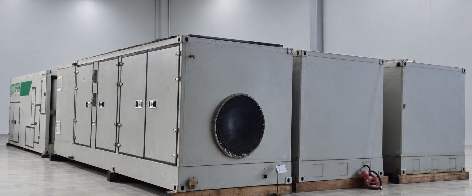
Opra OP16 series containerized gas turbine generator sets.
Quantity: 6 sets available.
Models in this group: OP16-3A and OP16-3B.
Procured in 2017 and 2018.
Unused: kept in controlled indoor warehouse storage since acquisition and preserved in ex-factory condition.
Written technical documentation and product conformity certificates can be furnished at handover.
The OP16 is a 2 MW-class single-shaft industrial gas turbine, standardized as a 20-foot containerized, skid-mounted, integrated generator set package.
The engine is built in three combustor versions, 3A, 3B and 3C. The base engine outputs of the OP16-3A and OP16-3B are essentially identical; they differ only in the combustion system installed.
Core Technical Specifications
Rated electrical power output: 1,850 kWe to 1,876 kWe (approx. 1.85 MW to 1.88 MW), ISO conditions; base power of 3A and 3B essentially identical.
Power (ISO): 1866 kWe.
Electrical efficiency: 25.1% (ISO operating conditions); power generation efficiency 25%.
Combined heat and power (CHP) efficiency: over 90% with exhaust heat recovery.
Pressure ratio: 6.7:1.
Exhaust gas temperature: 573 °C (1,063 °F).
Exhaust gas flow rate: 8.9 kg/s.
Time between overhauls (TBO): 42,500 hours (industrial heavy-duty design).
Weight: approx. 28 t.
Generator output voltage: 0.4 to 13.8 kV optional.
Generator frequency: 50/60 Hz optional.
Multi-unit parallel capacity: up to 10 to 12 MW in a modular containerized parallel configuration.
Synchronous generator, 50 Hz, 10.5 kV, 2,312 kVA at 15 °C (power factor 0.8).
4-pole, 3-phase.
Class F insulation, Class F temperature rise.
Air-cooled, with integrated brushless exciter.
Scope Of Supply, Each Set
OP16 gas turbine: complete unit including integrated reduction gearbox with overload protection and auxiliary drive devices.
Combustion system: gaseous fuel system with stainless steel piping, pressure and temperature transmitters, strainers and filters, flow control valve, shut-off valves and fuel nozzles.
Generator: as described above.
Turbine-generator base frame: heavy-duty structural steel base frame with integrated lube oil reservoir, gas turbine and generator mounting pads, and mounting locations for the starting, fuel and lubrication systems.
Output coupling: standard flexible coupling and steel coupling guard, with supporting structures and fastening bolts.
Lube oil system: main engine-driven lube oil pump, suction strainer, oil distribution module, relief valve, air-cooled oil cooler radiator, motor-driven auxiliary pump, oil piping and flexible hoses.
Starting system: hydraulic system with variable displacement piston pump, electric motor, relief valve, axial piston hydraulic motor, suction strainer, hydraulic hoses and piping.
Fuel gas system: fuel gas flow regulating valve, motorized shut-off and vent valves, combustor, fuel nozzles and fuel piping.
Ignition system: high-energy ignition exciter, ignition cables and spark plugs.
Bird screen at the air intake housing.
Gas turbine monitoring instrumentation: vibration probes, speed sensors, pressure transmitters and temperature sensors.
Unit control system: control console with solid-state logic for start-up and shutdown sequence, speed governing, gas turbine protection, generator protection, generator synchronization, alarms, status indication and operator interface; based on the Siemens control and information platform; control cabinet mounted off-skid.
MCC cabinet: power supply for the gas turbine auxiliary electrical equipment and the unit control panel (UCP).
Additional operator interface: an external PC can be connected to the control cabinet HMI through the identical HMI software.
Integral control room, installed adjacent to the generator side of the OP16 enclosure.
Enclosure: structural steel acoustic enclosure with access doors and platforms for inspection and maintenance, mounted directly on the base frame, with interfaces for turbine air intake, ventilation and oil cooler air, ventilation exhaust, turbine exhaust, control wiring and generator cabling; noise attenuated to 85 dB(A) at 1 meter.
Ventilation system: air intake filtration with replaceable filter elements.
Inlet air filter, silencer and ducting: combustion air filtration section with replaceable elements and steel ducting to the turbine inlet silencer and air intake flange.
Gas detection system: combustible gas detectors at the enclosure ventilation outlet, interfaced with the control console display and the safety shutdown system.
Air paths: ventilation air inlet, turbine combustion air inlet, oil cooler and generator air outlet, ventilation air outlet.
Components: ventilation air filter elements, turbine inlet air filter elements, ventilation silencer, turbine inlet air silencer, ventilation exhaust silencer, gas detection module, inlet and outlet fire dampers, generator and oil cooler silencer.
Fuel Flexibility
High calorific value fuels: natural gas, wellhead gas, propane, LPG, diesel, crude oil, aviation kerosene, synthetic fuel.