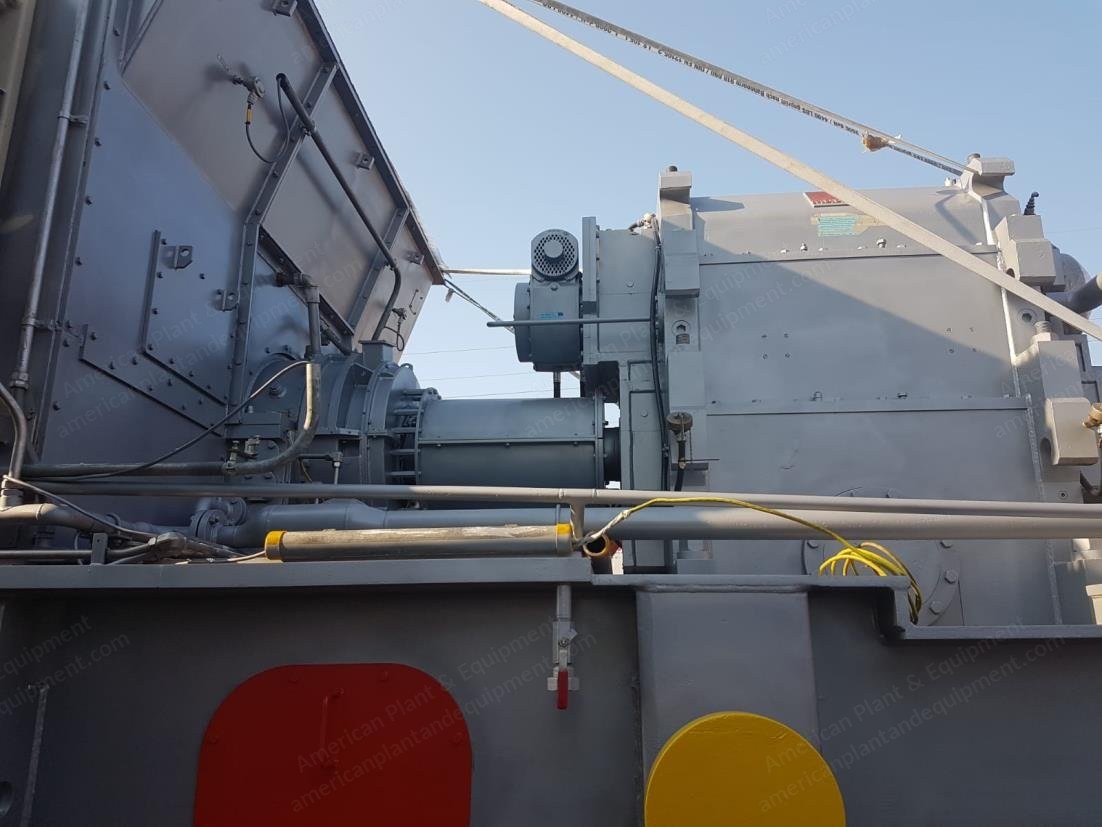
General Electric, LM6000 PB DLE, 53 MW Combined Cycle Power Plant, Siemens Steam Turbine, Brush Generator
Scroll to zoom
100%
Description
Overview
Dismantled and stored combined heat and power plant.
The combined cycle plant consists of a gas turbine, waste heat recovery boiler, steam turbine and a generator mounted in a single shaft configuration.
The capacity of the installation (without steam delivery) is 53 MW (ISO conditions).
The efficiency (without steam delivery) is 48.3% (ISO conditions).
Gas Turbine
The prime mover of the installation is an aero derivative General Electric LM6000-PB-DLE.
The GT is equipped with a dry low emission combustion chamber which guarantees NOx emissions of 32 gr/GJ and CO2 emissions of 1.6 kg/h.
The rated power of the GT is 40 MWe at an efficiency of 40%.
The GT is equipped with a hydraulic starter make Hagglunds drives.
The GT has its own lubricating oil system.
The GT is via a gearbox direct coupled to the generator.
Make: General Electric.
Type: LM6000 PB DLE.
Capacity: 40 MW.
Fuel: low caloric gas.
NOx suppression: DLE combustion chamber.
Number of burners: 90.
Nominal fuel: 12000 m3n/h.
Nominal capacity GT: 40.0 MWe.
Efficiency GT: 40.0%.
Steam Turbine
The steam turbine is a Siemens ENK40/53-3, with a capacity of 13 MWe.
Make: Siemens.
Type: extraction condensing turbine.
Speed: 7135 RPM.
Capacity: 12.3 MW.
Extraction pressure 1: 13 barg.
Extraction temp 1: 210 °C.
Extraction pressure 2: 3 barg.
Extraction temp 2: 160 °C.
The HP steam is led to the HP steam turbine. Via regulsteam at the outlet of the HP turbine is mixed with the LP steam. The outlet steam has a pressure of 0.1 bar and is carried off the condenser.
The steam turbine has two drains for the delivery of the heat. The HP drain has a pressure of 13 bar at 210°C. The maxi LP drain, which is between the HP and the LP turbine has a pressure of 4 bar and a temperature of 149°C. The maximum mass flow of the LP drain is 50 ton/h (13.9 kg/s).
The ST has its own lubricating and hydraulic system.
The ST is coupled to the generator via a gearbox and a SSS clutch.
Generator
Make: Brush.
Type: synchronous.
Speed: 3000 RPM.
Voltage: 10.5 kV.
Capacity: 63.5 MVA.
The generator is equipped with a separate exciter.
The generator mounted between the gas turbine and the steam turbine, is a 2 pole (3000 RPM) synchronous Brush generator, type BDAX8-355PRH.
This air-cooled generator has a capacity of 64 MVA at 10.5 kV.
The generator is equipped with its own lubricating oil system.
Air Cooled Condenser
Exhaust steam from the steam turbine goes to the air-cooled condenser (make: GEA), mounted on the roof of the auxiliary boiler house.
To create vacuum, the condenser is equipped with a hogging ejector.
To hold the vacuum there is a redundant two stage holding ejector available.
Balance of Plant
The balance of the installation consists of all what is needed to keep the installation running.
Feed Water
The feed water is de-aerated in a feed water tank.
From there the water goes via a heat exchanger to the redundant LP and HP feed water pumps.
These pumps transport the water to the LP and HP economizers of the boiler.
Demi-Installation
The installed demi-installation is an ion exchanger installation, make Envitec.
The installation consists of: a kathion ion exchanger, anion ion exchanger, mixed bed ion exchanger, intermediate and storage tanks, acid and caustic storage tanks and a neutralization tank.
The ion exchangers are redundant, which means that the production of the demi-water continues when the other ion exchanger is regenerated.
The capacity of the demi-installation is 60 ton/h continuous.
Water Quality
The water quality supervision is concentrated in the water room.
All necessary measurements are carried.
The results of the measurements are presented in the DCS.
Closed Cooling Water
For the cooling of the diverse systems of the internal closed cooling water system is installed.
This system consists of a circulation system filled with 50% glycol and 50% demi-water.
The cooling of the system takes place in the air coolers mounted next to the air-cooled condenser.
Cooling water is used to cool the lubricating oil, the generator, the water quality, etc.
Air Compressors
For the production of working air and instrument two Atlas Copco air compressors are installed.
Fire Detection and Extinguishing
The fire detection installation is delivered by Siemens covers the entire installation.
Fire extinguishing is divided in two systems: inert gas and micro-drop.
The inert gas installation is used for: GT package, step-up transformer, MCC room, auxiliary transformer room, control equipment room, operator room.
The micro-drop extinguishing is driven by an extinguishing pump in the demi-water room and is used for: lube oil steam turbine, steam turbine, generator, lube oil generator, lube oil gas turbine.
Electrical Installation
The generator produces electricity at 10.5 kV.
For own use two dry transformers are installed, one 10.5 kV/400 V and another 10.5 kV/690 V.
In case of emergency (loss of grid connection) the installation is equipped with 110 V = batteries for the emergency lub-oil pumps and 24 V = batteries for the DCS.
Process Automation DCS
The overall automation system for the installation is a Siemens TXP (T2000).
This system holds the superior logic and all controls, alarms and trips for the complete installation.
The separate automation systems (gas turbine, steam turbine) are controlled via T2000 system.
Also, all criteria in the separate automation systems (including events and alarms) are collected in the T2000.
Specifications
Gas turbine serial: 190-204
Request a Quote
✓
Request sent
Thank you, our team will reply to you shortly.
Direct access to our team
Email American Plant & Equipment
Tell us what you want to buy, source, finance, or sell. A machinery specialist will follow up with you.
✓
Thank you. Your request is with the American Plant and Equipment team.
A machinery specialist will follow up with you.
Machinery updates
Subscribe to our email list
Tell us which industries you follow and we will send you the machines that match.
✓
You are on the list.
We will email you when machines that match your interests come in. Unsubscribe from any message.