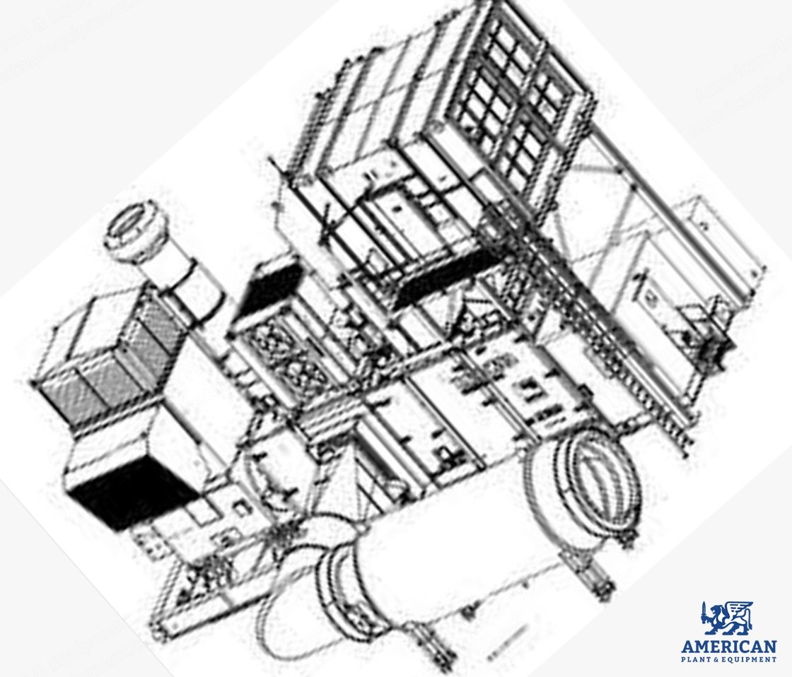
Houses unit control panel suite and co2 extinguishing
Interior lighting
Airconditioned
Exhaust System
Side exit
Primary compensator
Thermal/acoustic shroud
75db(A) silencer
Fire Protection and Gas Detection Systems
Four-zone fire monitoring equipment
Co2 storage and co2 discharge nozzles
Infra-red (3) and heat (rate/rise) detectors (2)
Shut-off damper at ventilation system discharge
Two-level gas detection
En54 / iso 6183 compliant
On-Skid Control Panels
Gas turbine control and protection section: allen bradley “controllogix” plc, digital engine management system, control, monitoring and protection (pressures, temperatures, vibration, etc), remote communication, system graphics, on-skid hmi, modular distributed i/o, data communication link (modbus protocol over tcp/ip)
Motor control centre: single 400V, 50Hz, 3ph connection, a.c. power distribution for the generatorset, motor starters and protection, distribution mcb's for auxiliary a.c. supplies, skid-mounted allowing a single point of contact for the customer
Battery charger and uninterruptible power supply: battery charger and ups 24Vdc supply to control systems, to power lube oil pump for 3 hours after loss of a.c. supply
Generator control and protection section: electronic automatic voltage regulator, digital integrated protection relay comprising: differential fault (87g/t), stator earth fault (51n), overcurrent (51), three-phase overvoltage (59), three-phase under voltage (27), reverse power (32), under frequency (81u), over frequency (81o), loss of excitation (40), negative phase sequence (46)
Synchronizing equipment section: auto and check synchronizers, selector switches, bus voltmeter, and synchroscope, automatic or manual forward and back synchronizing, mv circuit breaker control
Request a Quote
✓
Request sent
Thank you, our team will reply to you shortly.
Direct access to our team
Email American Plant & Equipment
Tell us what you want to buy, source, finance, or sell. A machinery specialist will follow up with you.
✓
Thank you. Your request is with the American Plant and Equipment team.
A machinery specialist will follow up with you.
Machinery updates
Subscribe to our email list
Tell us which industries you follow and we will send you the machines that match.
✓
You are on the list.
We will email you when machines that match your interests come in. Unsubscribe from any message.