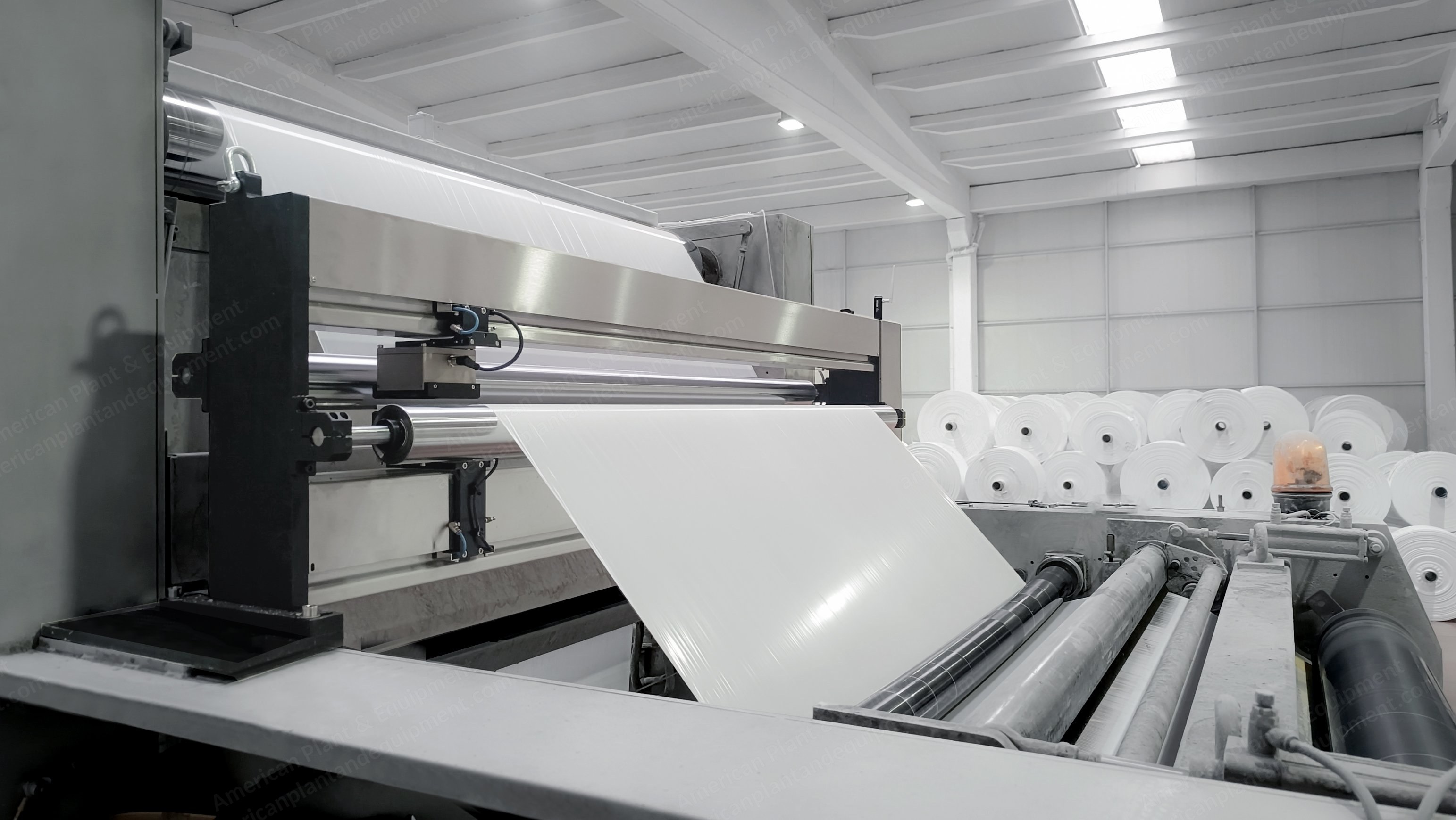
Basis weight measurement system utilizing ultrasonic technology
Non-woven basis weight measurement gauge system
System utilizes an o-frame, ultrasonic transmission sensor and receiver to measure the product basis weight
Continuous scanning system to provide constant feedback for cd (cross direction) weight variation and md (machine direction) weight variation
Preliminary Customer Machine Data
Type: non-woven
Weight: 4 oz/yard (135.6 gsm)
Width: 80” max
Operator Interface
Industrial pc – qty 1: windows 11 pro operating system, ascii keyboard and mouse
Operator console – qty 1: floor mount pedestal enclosure to house pc and touchscreen
23.8” touchscreen monitor
Industrial folding keyboard to withstand environmental conditions
System Application Software
Hmi software is pc based on.net and postgresql
System and application software stored on flash disk in the beckhoff controller
Management Information System Software Package
Composite web profiles (cumulative averages) of measurements by linear dimension or by control zone
Last scan profiles of coat weight by linear dimension or by control zone
Machine direction trends
Recipe storage and selection
Trend data with historian compatibility including machine direction and cross web profiles
Batch report package
Maintenance pages
Color maps (2d and 3d)
Indicator page
Quarantine page for removal of data of discarded portions of rolls on roll reports
Log page
Alarm page
Automatic pdf report generation
Hardware
Scanning frame – qty 1 (electrical components housed in the end of scanning frame): o-frame style, scanning width for 80” maximum product width, internal cabling, servo motor, limit switches, proximity and other auxiliary sensors, cable terminals and all internal system cables, miscellaneous hardware, local push button station located on operator side of frame
Emergency stop button – one on each side of scanning frame
Scan button
Park button
Jog selector switches
Gauge controller
Beckhoff i/o modules
Ac drive for frame motor
Led light column for status
Voltage distribution
Power supply
Measurement Sensor
Ultrasonic transmission – transmitter and receiver
Commissioning
Up to (3) 10-hour days
Travel and expenses included
Project Services
Project management, with kick-off meeting when project starts
Complete engineering of hardware including the overall system structure, hardware specifications, cabinet layouts etc.
Application software build
Factory integration test, 1 day (system is built and testing in turkey) if a us based fat test is required, please let us know so we can add this to the quote
Operator training - during commissioning phase
Maintenance training - during commissioning phase
Onsite Services
System check-out and commissioning
A single trip is included in the project
Online calibration check with the customer lab for those grades which will be running during the start-up period
Operator training - during commissioning phase
Maintenance training - during commissioning phase
Miscellaneous
The enclosures containing the drive, controller and i/o modules will be placed near the scanner, taking into consideration sensor cable length purchased
The operator control station will be placed in the designated area
All system internal cables will be provided as part of project scope
Buyer's Responsibilities
Electrical and mechanical installation of equipment at desired locations: scanning frame, control panel, operator station etc.
Supply of electricity, conditioned dry air, network connection and cable
Running of conduit and air lines where required
Support from lab for on-line calibration
Documentation
Standard manuals: operator manual, maintenance manual
Project documents: electrical schematics, mechanical drawings with parts list & exploded views
The supply of the documentation is in pdf file format
Request a Quote
✓
Request sent
Thank you, our team will reply to you shortly.
Direct access to our team
Email American Plant & Equipment
Tell us what you want to buy, source, finance, or sell. A machinery specialist will follow up with you.
✓
Thank you. Your request is with the American Plant and Equipment team.
A machinery specialist will follow up with you.
Machinery updates
Subscribe to our email list
Tell us which industries you follow and we will send you the machines that match.
✓
You are on the list.
We will email you when machines that match your interests come in. Unsubscribe from any message.